Model a desk robot arm: the nut
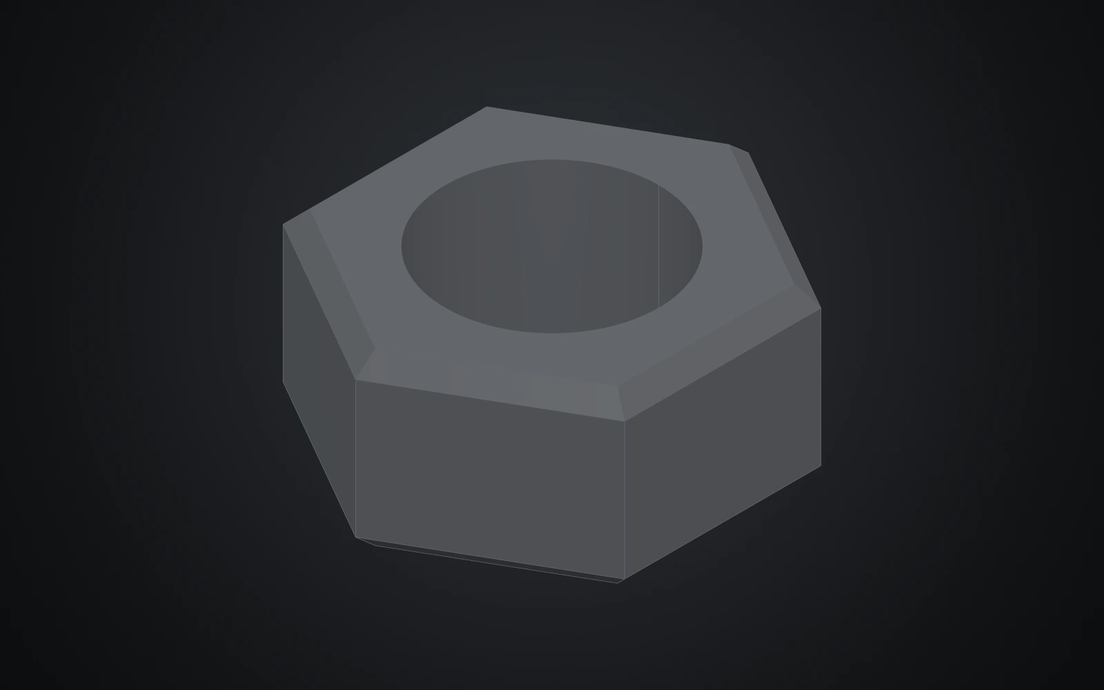
The nut is the last part, and parametric in its diameter like the screw, so it fits whatever bolt it is inserted for.
Each step shows the Designer as you make it: a feature's dialog filled in with the step's values, with the tutorial card ringing OK, or what the step made. The first time a command appears, a picture shows where it is. The step numbers match the card's in Help > Tutorials.
-
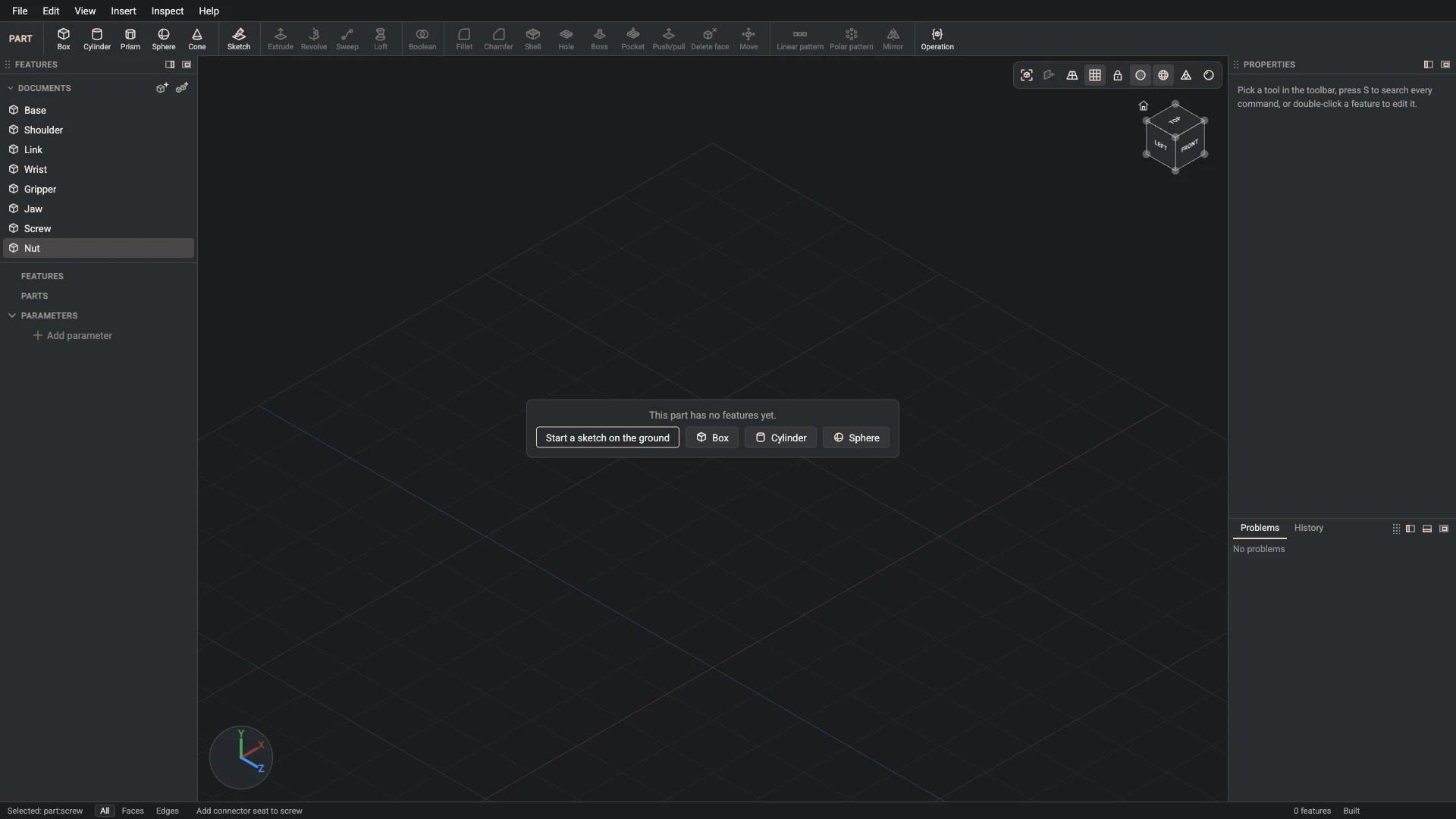
New part, from File > New part: name Nut.
A hex nut, parametric in its diameter, for the bolts through the arm's pivots.
-
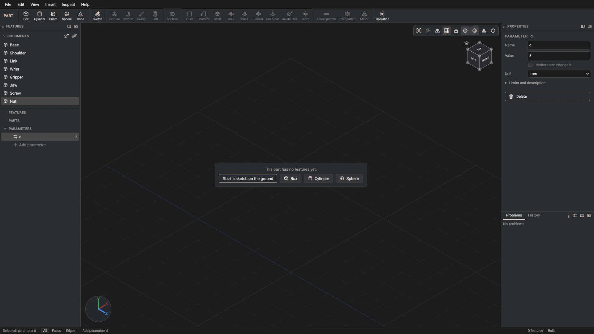
Parameter, from Insert > Parameter: name d, value 8, unit mm.
Add the parameter d, 8 mm: the diameter of the bolt the nut fits.
-
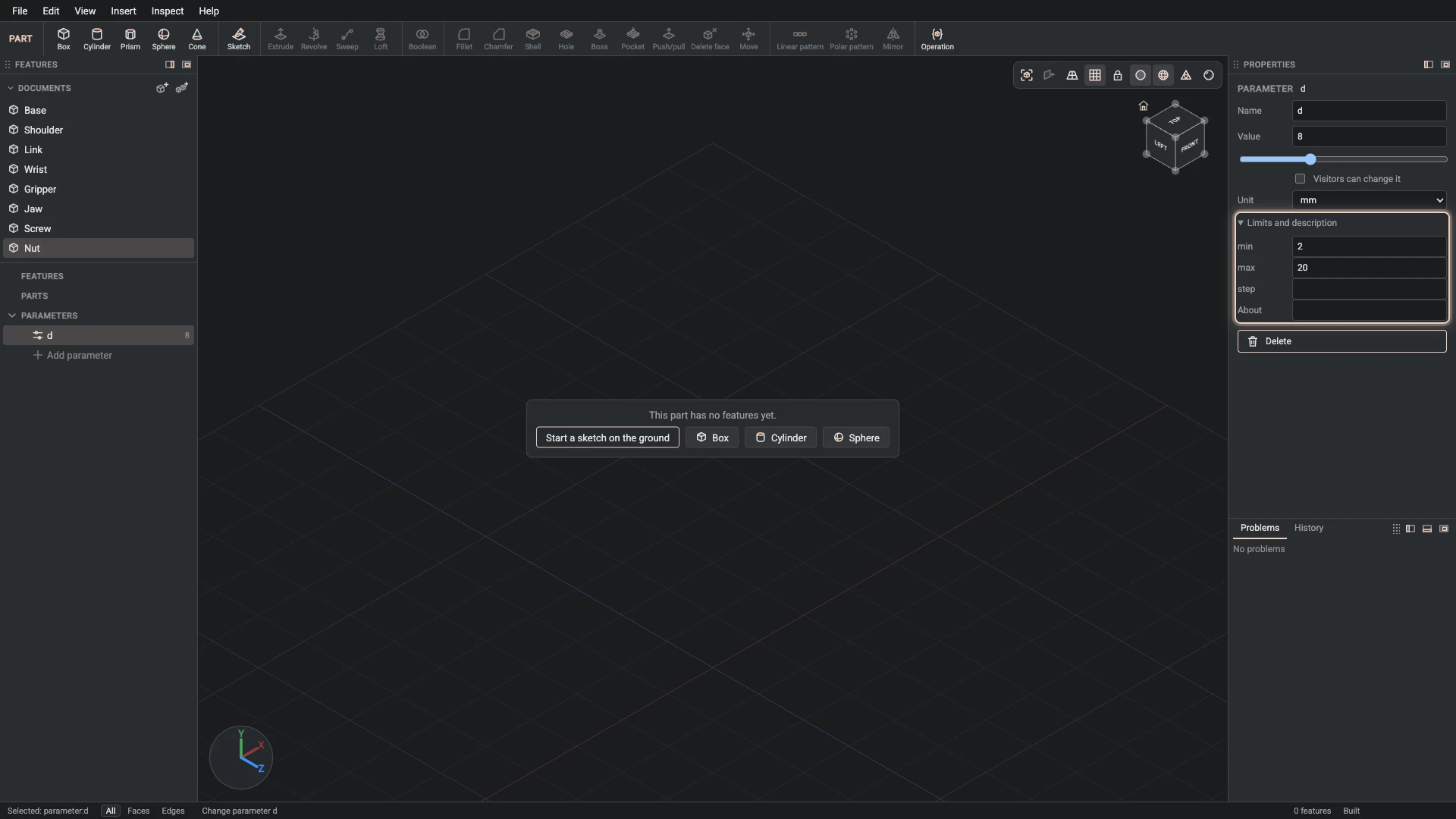
Change parameter, from the Properties panel: name d, min 2, max 20.
Give d its range, 2 to 20 mm: the values the design is drawn for.
-
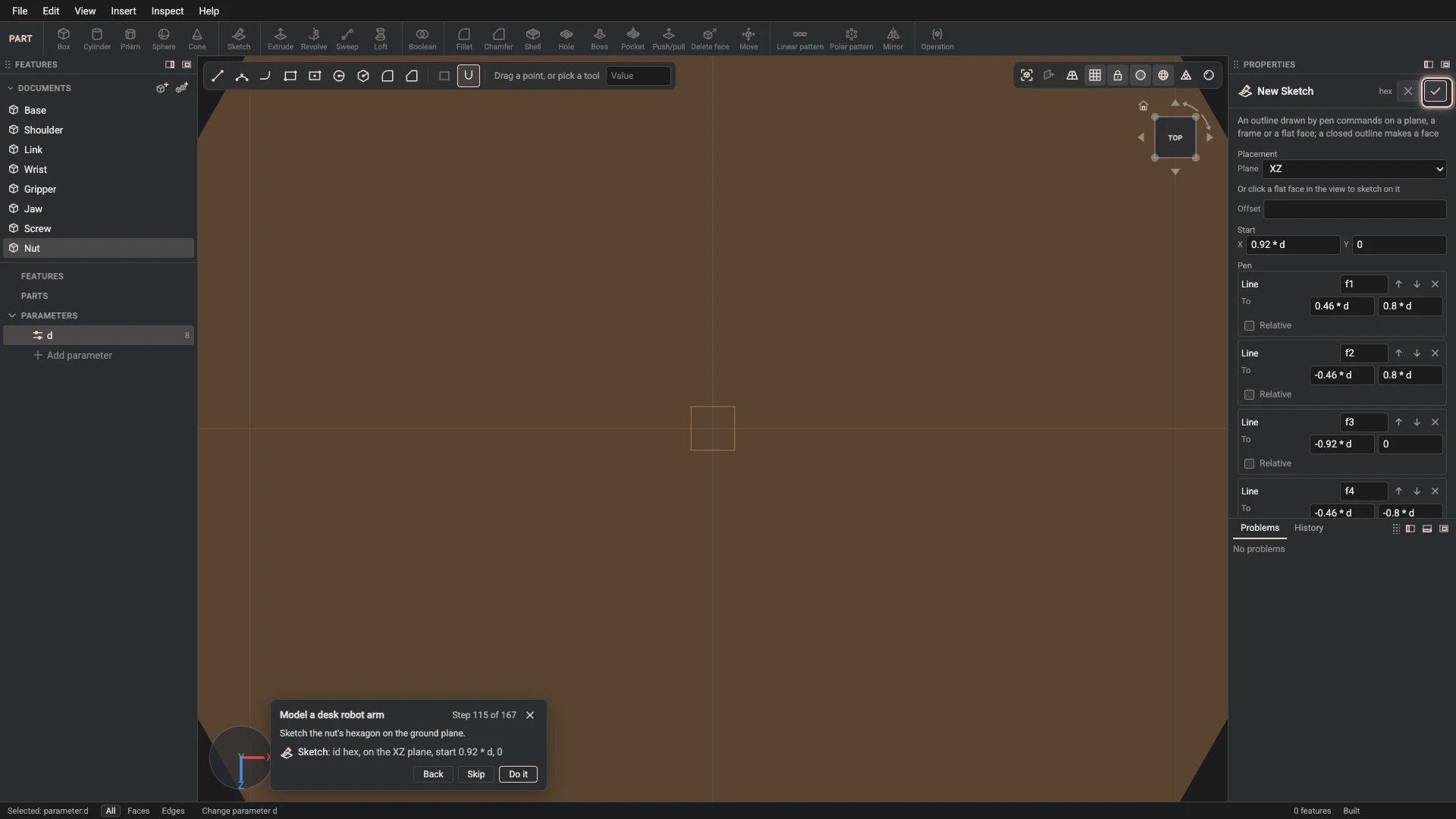
Sketch, from Insert > Sketch: id hex, on the XZ plane, start 0.92 * d, 0.
Sketch the nut's hexagon on the ground plane.
-
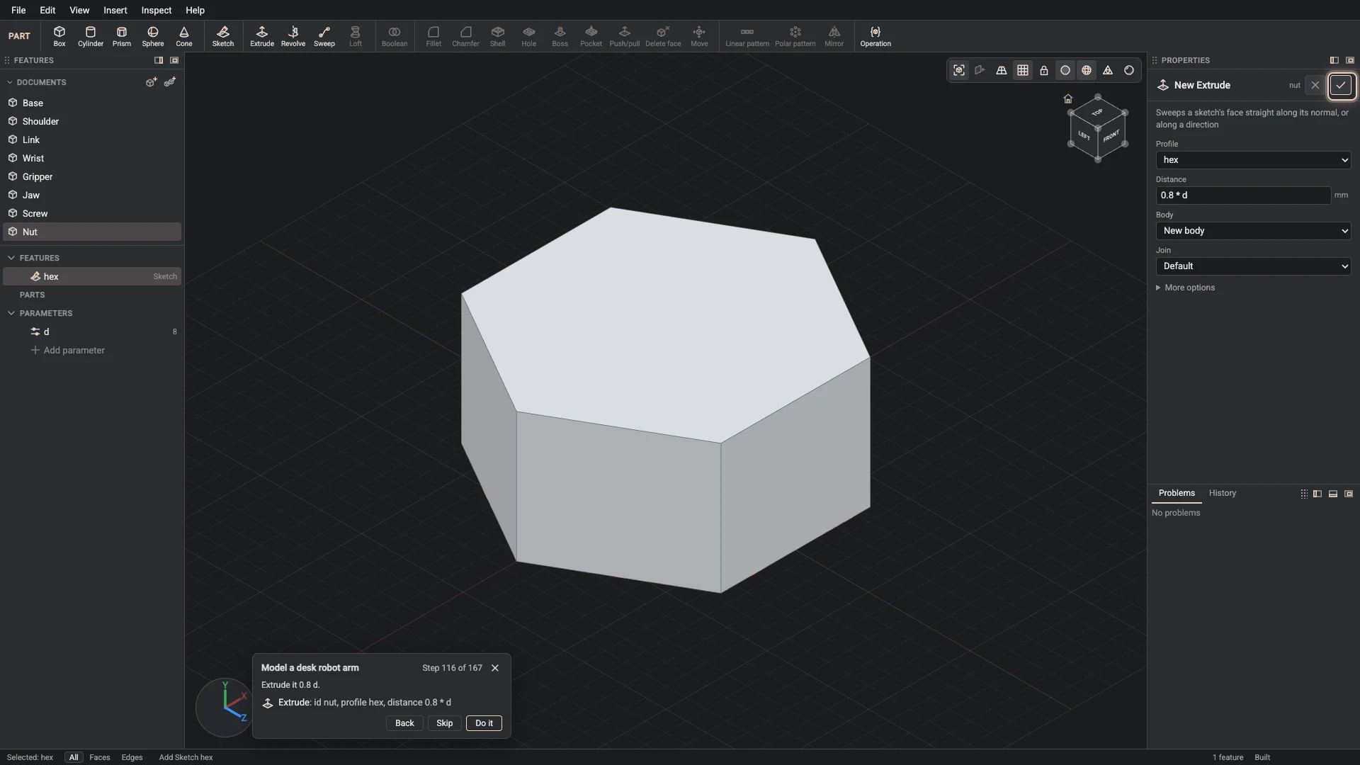
Extrude, from Insert > Extrude: id nut, profile hex, distance 0.8 * d.
Extrude it 0.8 d.
-
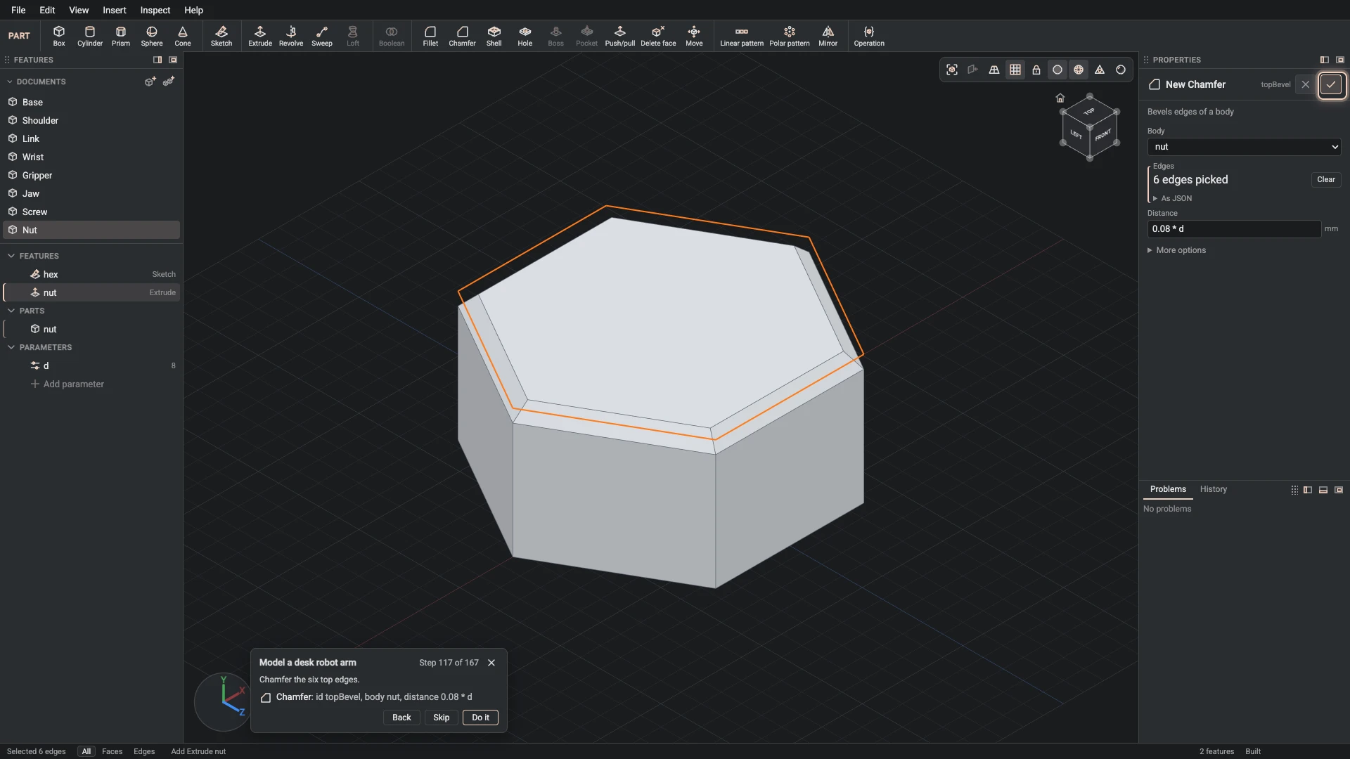
Chamfer, from Insert > Chamfer: id topBevel, body nut, distance 0.08 * d.
Chamfer the six top edges.
-
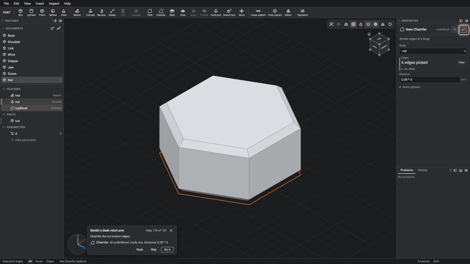
Chamfer, from Insert > Chamfer: id underBevel, body nut, distance 0.08 * d.
Chamfer the six bottom edges.
-
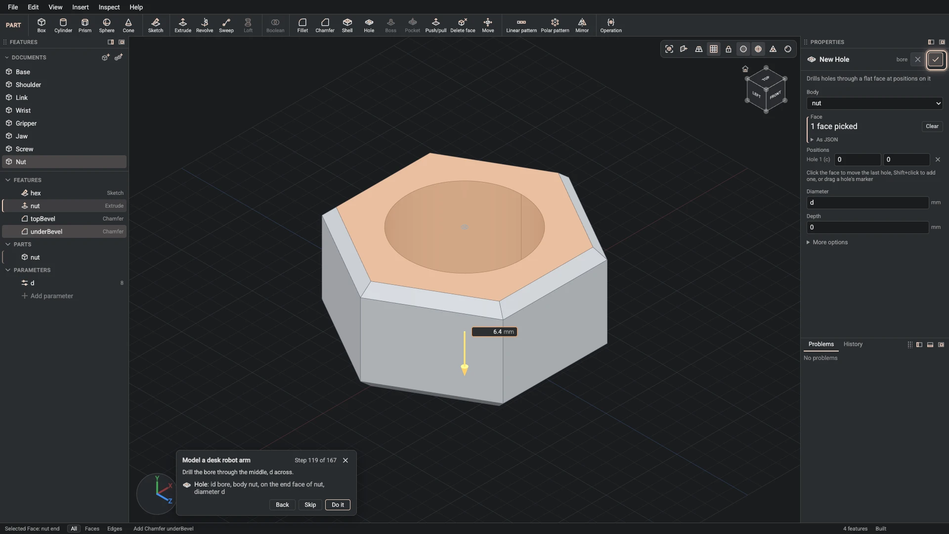
Hole, from Insert > Hole: id bore, body nut, on the end face of nut, diameter d.
Drill the bore through the middle, d across.
-
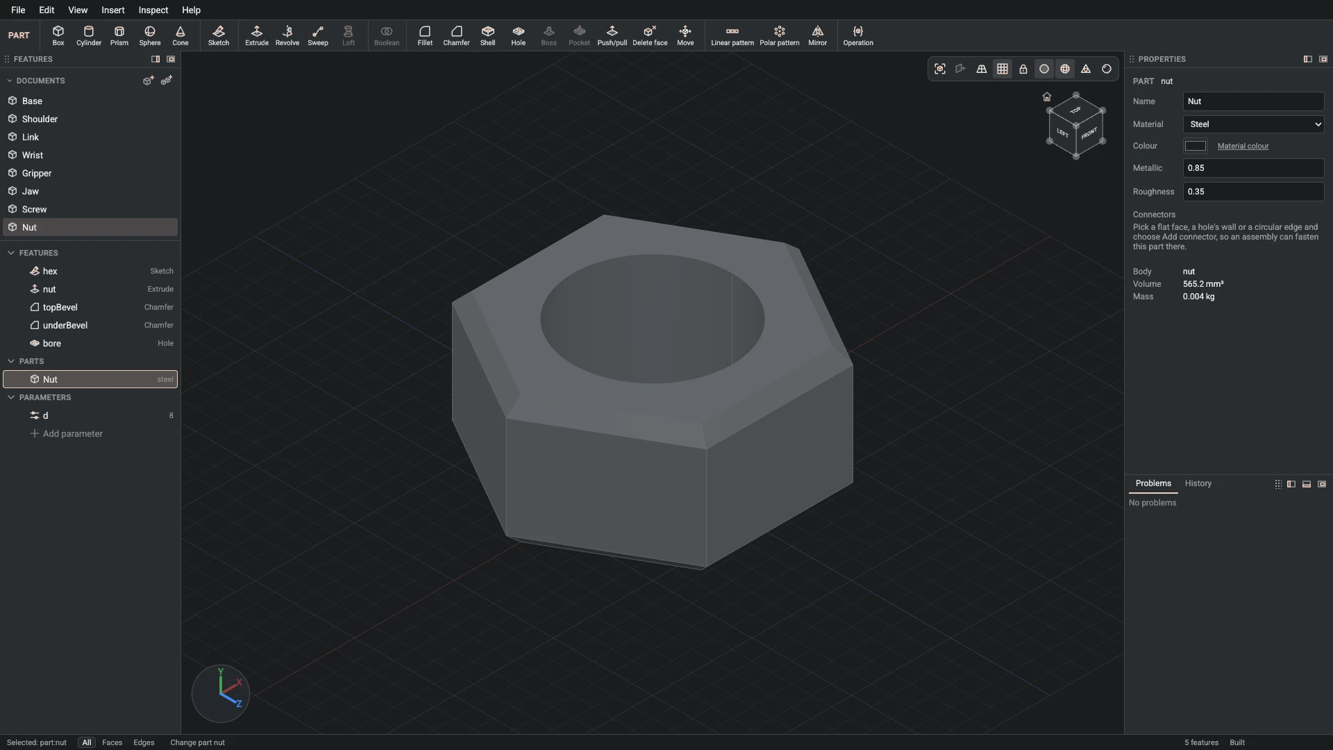
Part properties, from the Properties panel: id nut, name Nut, material steel, color #1d1f22, metallic 0.85, roughness 0.35.
Name the part Nut: black steel.
-
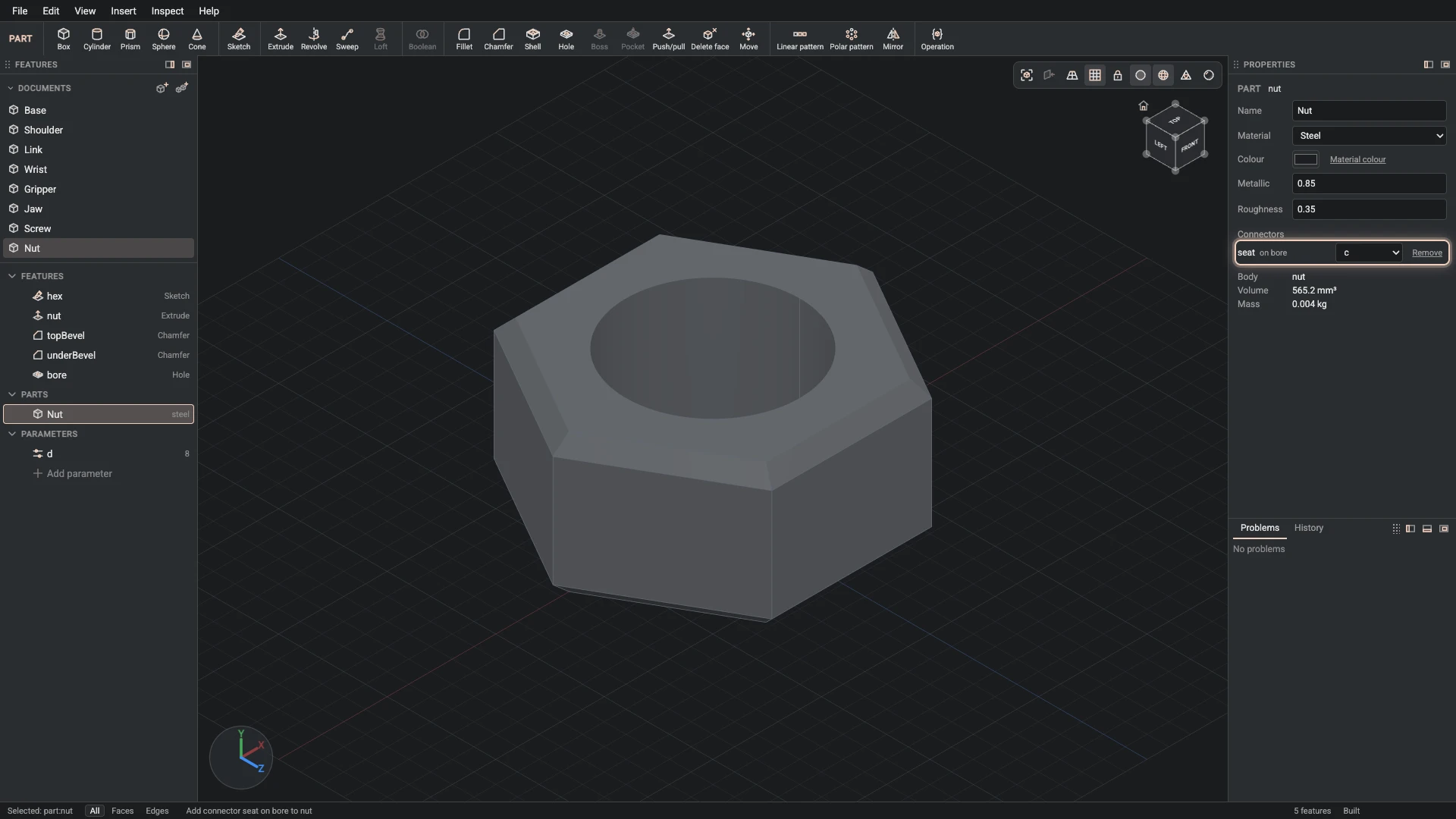
Add connector, from Insert > Add connector: part nut, id seat, on the start face of nut, axis the wall face of bore.
Add a connector on the underside, its axis along the bore.
Verified against the product in October 2026