Make your first part
In this tutorial you make a mounting plate: a flat plate with rounded top edges and a hole near each corner. It takes about ten minutes, and it shows the idea the whole Designer rests on. A part is a list of steps that read named values, so when you change a value later, every step that reads it follows.
You will:
- start a part document and give it three parameters;
- draw a sketch whose sides are those parameters;
- extrude the sketch into a solid;
- round edges and drill holes that stay where they belong;
- change one parameter and watch the whole plate follow.
You need the Designer open. The introduction says how to open it.
Play it in the Designer
The Designer plays this tutorial itself. Open Help > Tutorials and press Start beside Make your first part.
A card shows each step: what it does, the command with its values, and a ring around the control to use, or around its menu while the menu is closed. Make the step yourself, and the card moves on as soon as the Designer sees it done, however you made it. Do it makes the step for you; Back and Skip move without changing anything.
The steps below come from the same tutorial the card plays, so the page and the app always agree.
The steps
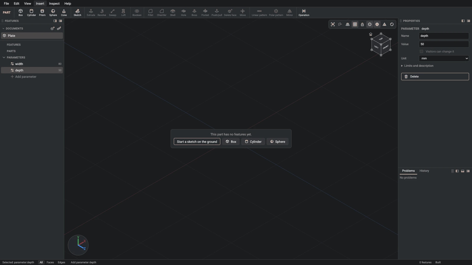
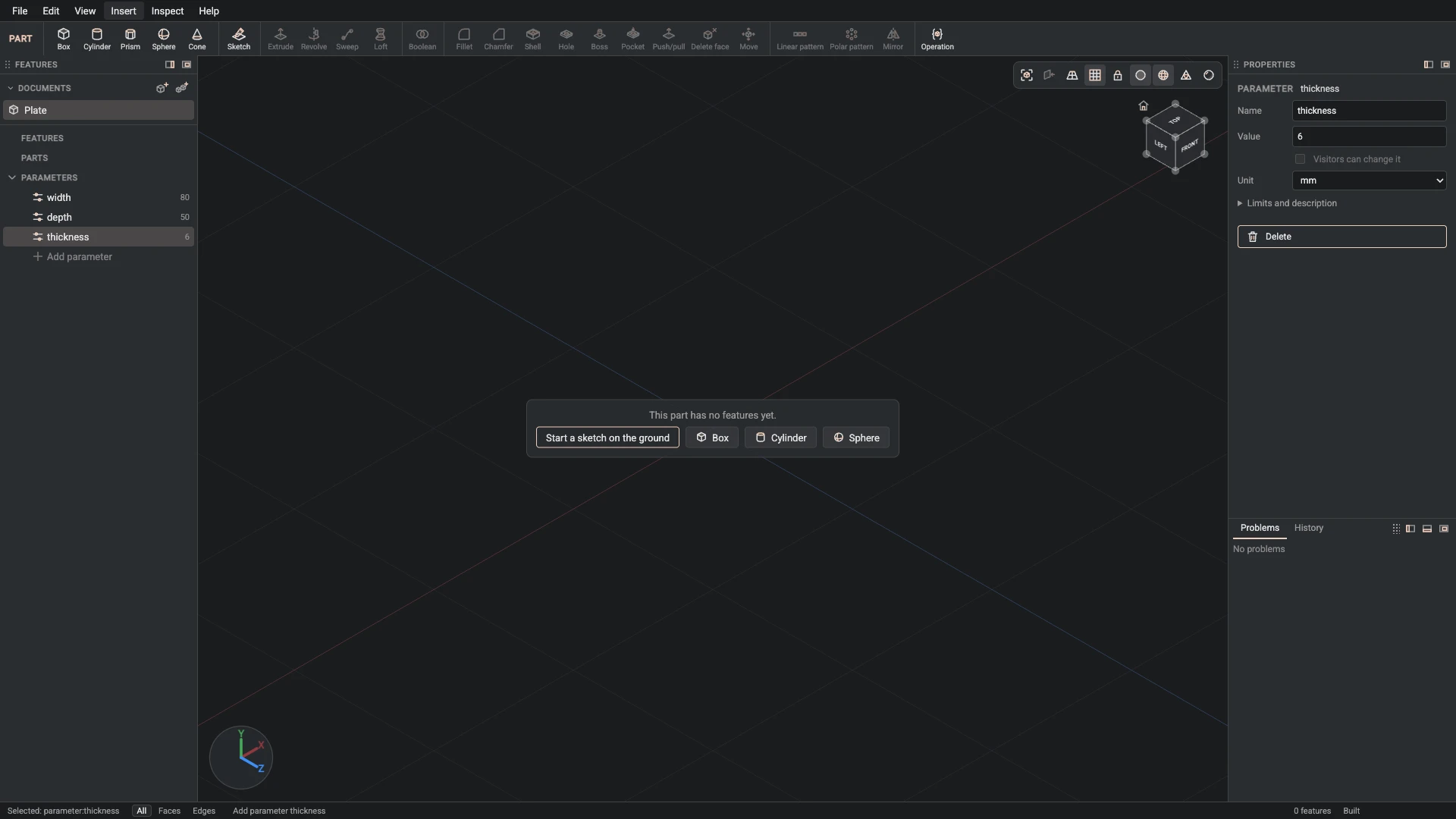
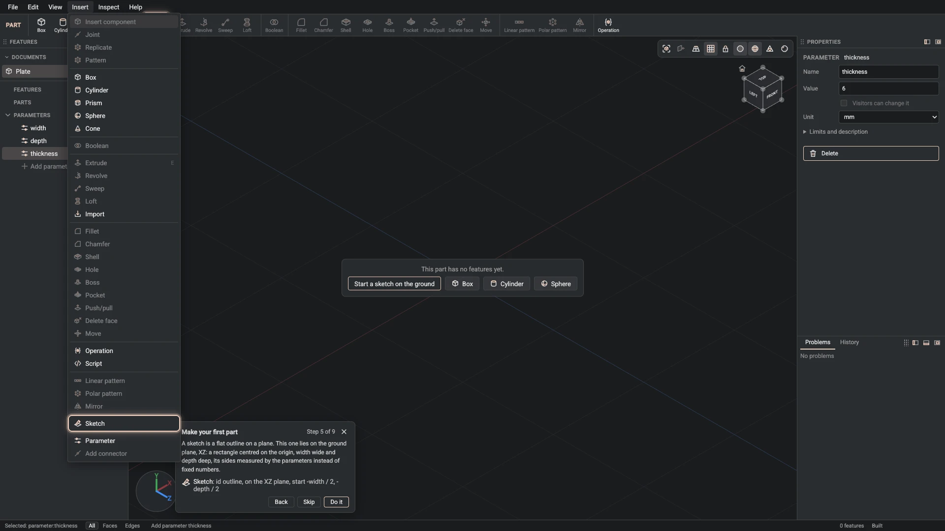
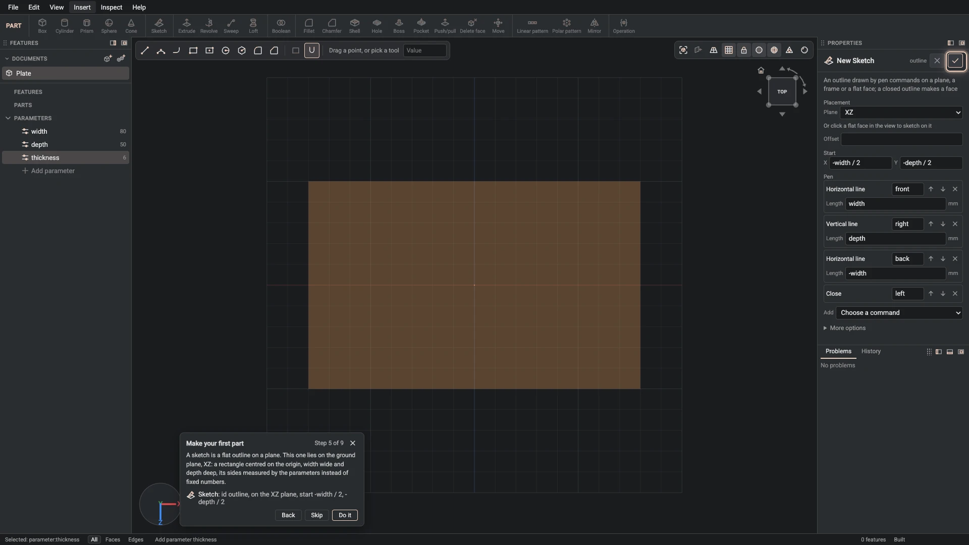
Each step names its command, where to find it, and the values to give it, and a picture shows it in the Designer: a feature's dialog filled in, with the tutorial card ringing OK, or what the step made. The first time a command appears, a picture shows where it is. Click a command's name for everything it takes. A value such as width / 2 is an expression: type it as it is, and the Designer works it out from the parameters.
Plate
-
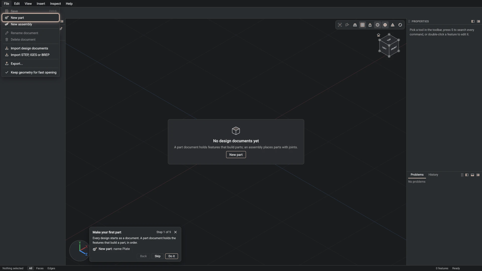
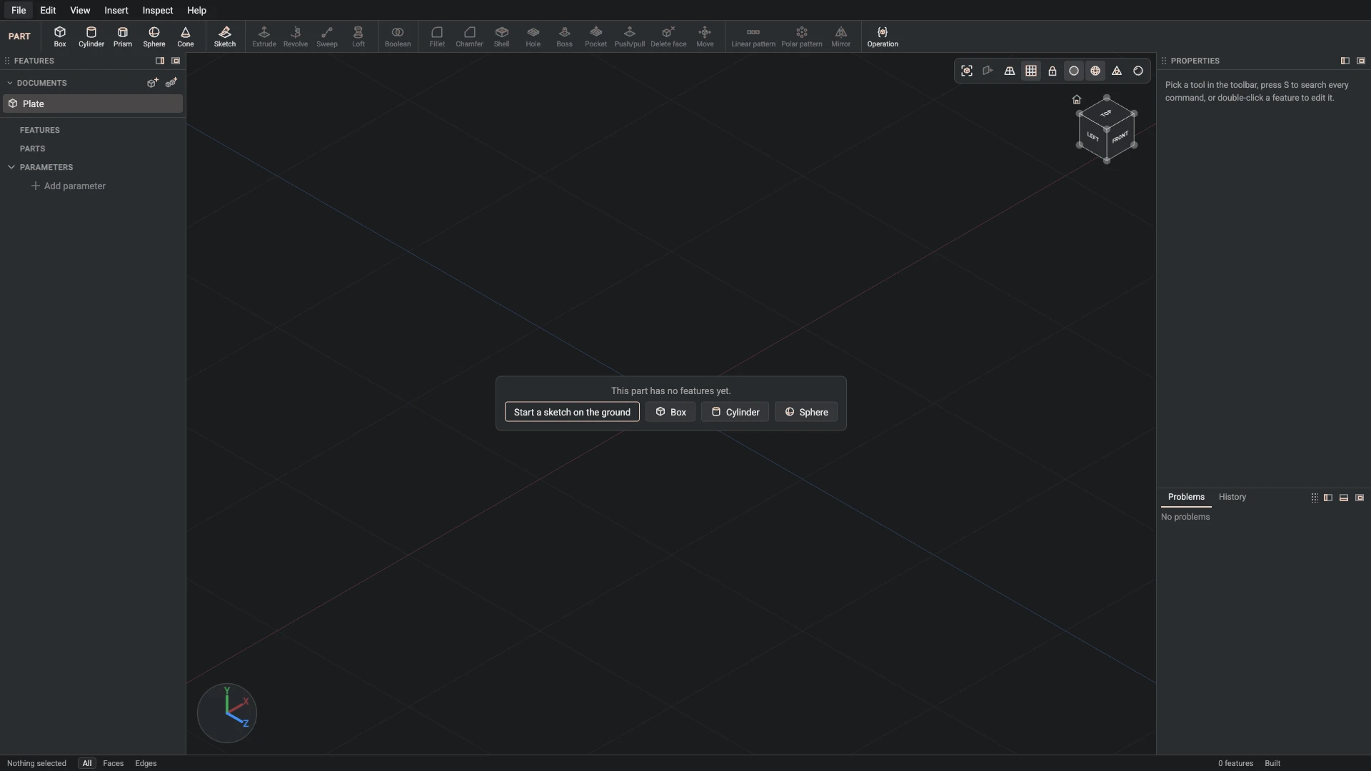
New part, from File > New part: name Plate.
Every design starts as a document. A part document holds the features that build a part, in order.
-
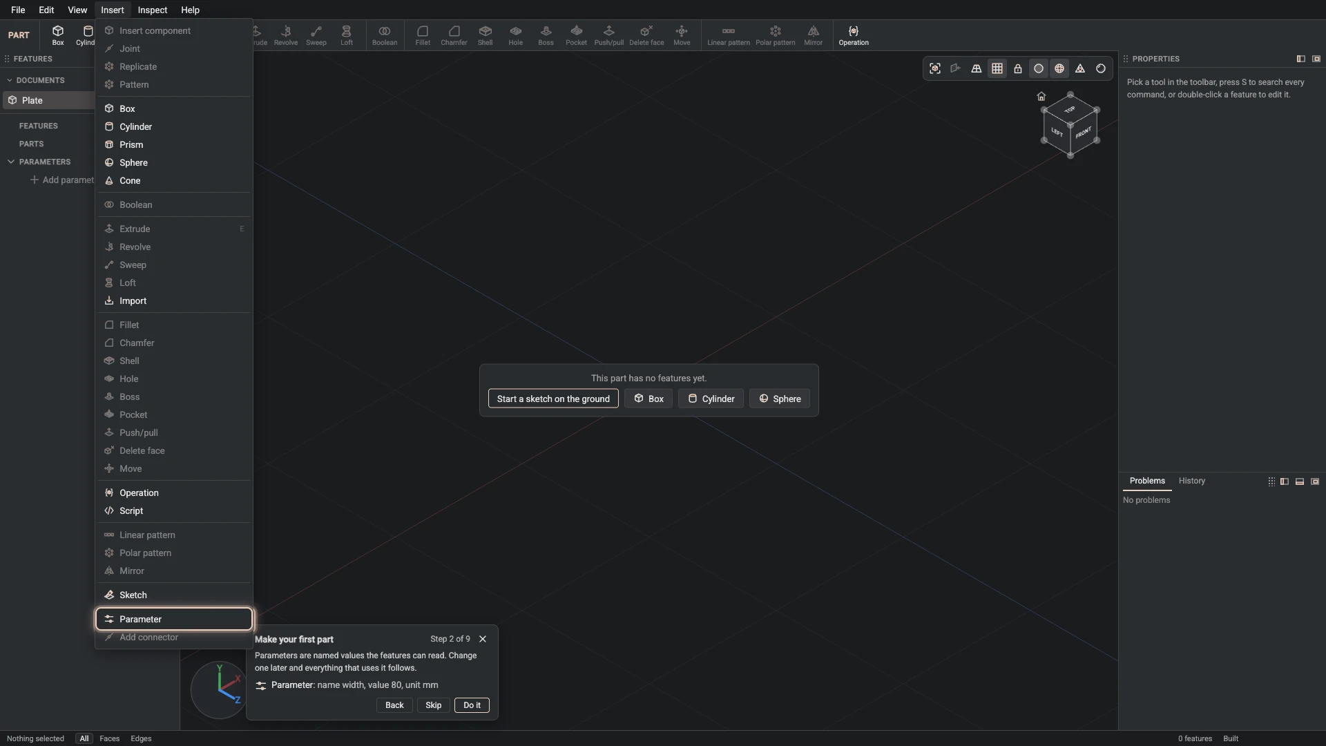
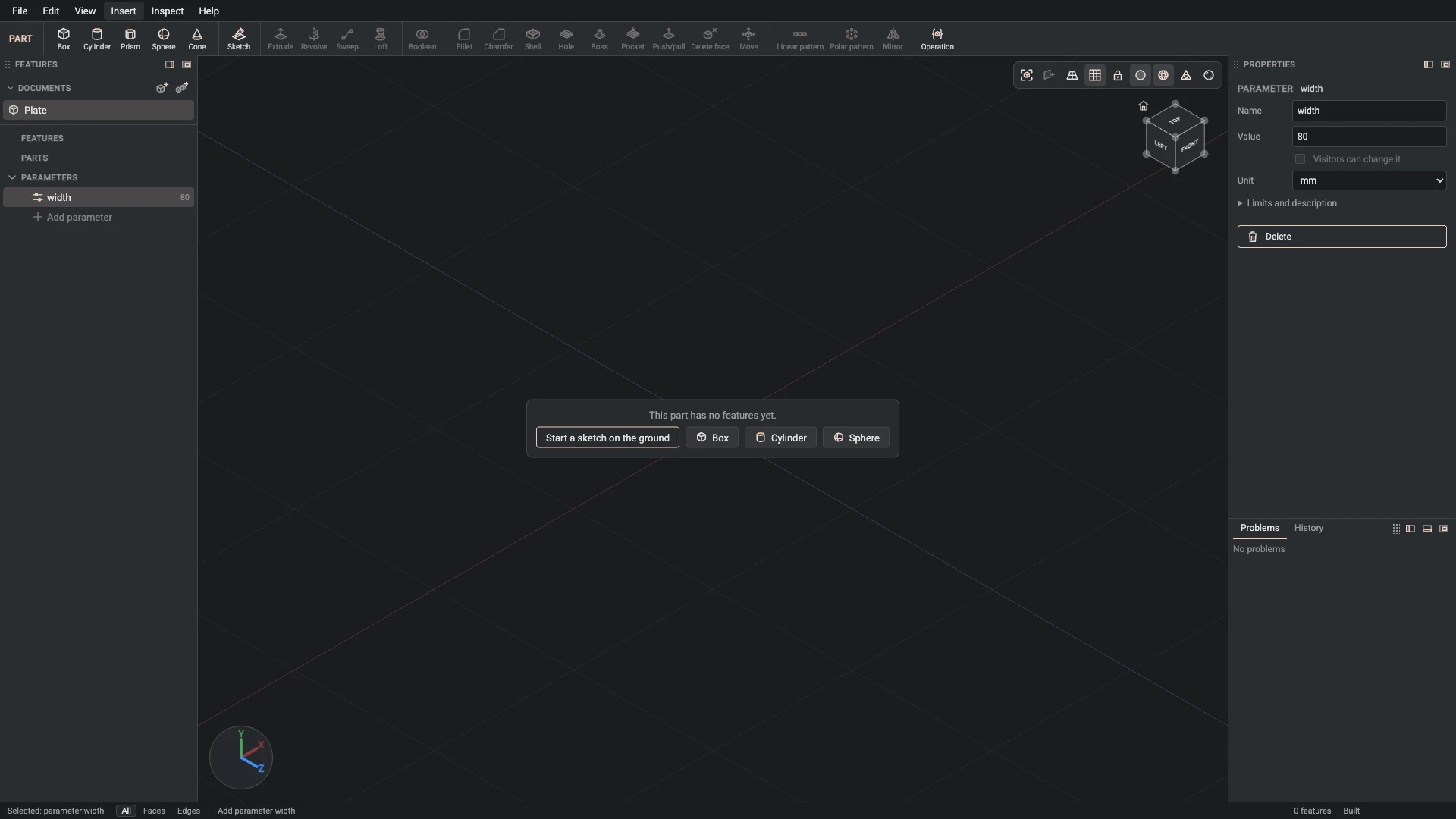
Parameter, from Insert > Parameter: name width, value 80, unit mm.
Parameters are named values the features can read. Change one later and everything that uses it follows.
-
Parameter, from Insert > Parameter: name depth, value 50, unit mm.
A second parameter, depth, for how deep the plate is.
-
Parameter, from Insert > Parameter: name thickness, value 6, unit mm.
And a third, thickness, for how thick it is.
-
Sketch, from Insert > Sketch: id outline, on the XZ plane, start -width / 2, -depth / 2.
A sketch is a flat outline on a plane. This one lies on the ground plane, XZ: a rectangle centred on the origin, width wide and depth deep, its sides measured by the parameters instead of fixed numbers.
-
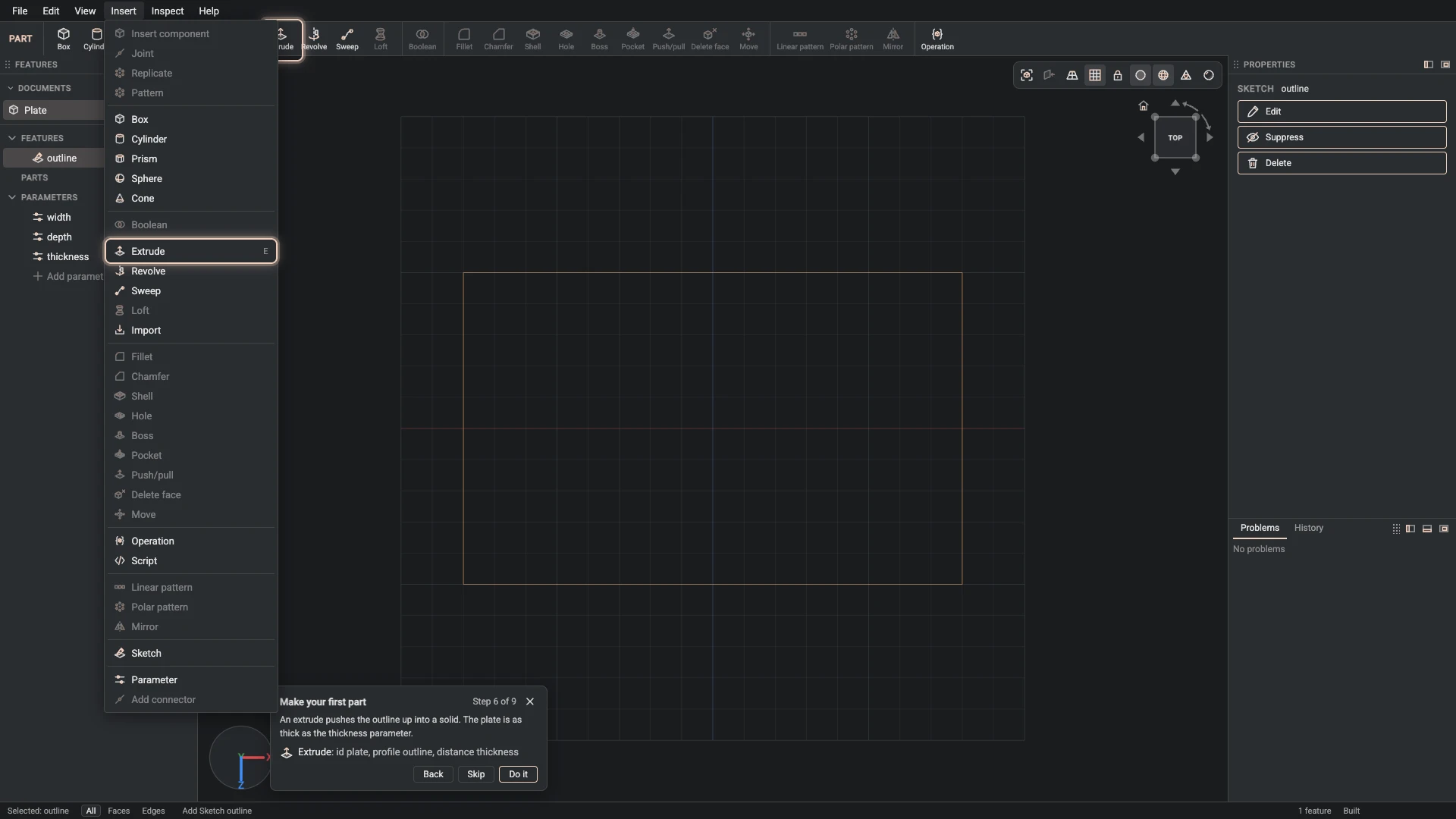
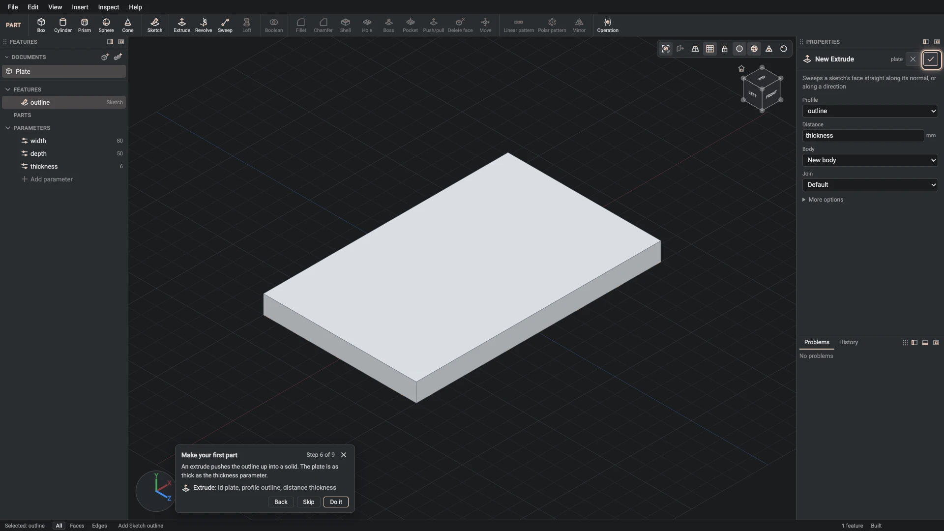
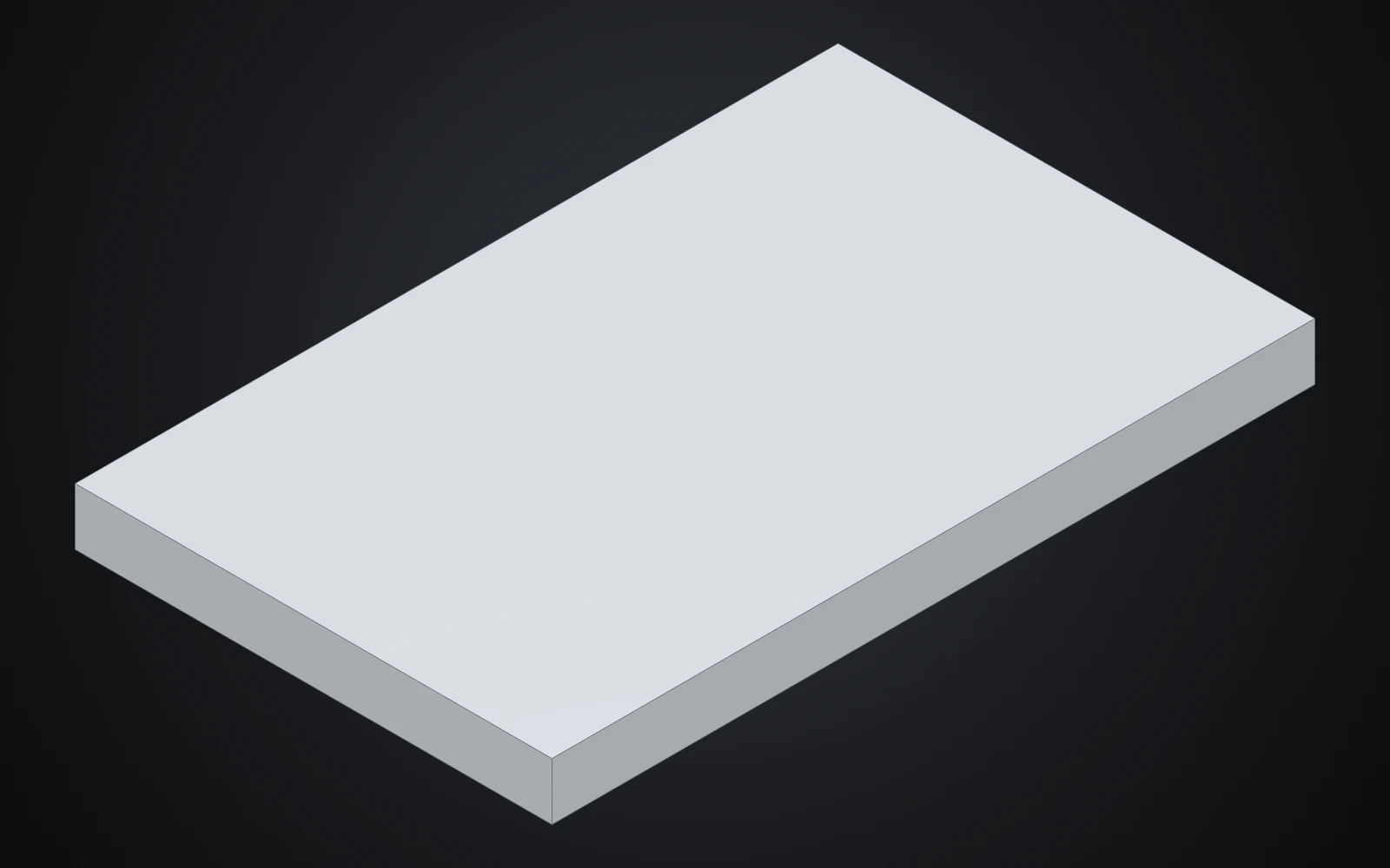
Extrude, from Insert > Extrude: id plate, profile outline, distance thickness.
An extrude pushes the outline up into a solid. The plate is as thick as the thickness parameter.
Rounded edges and holes
-
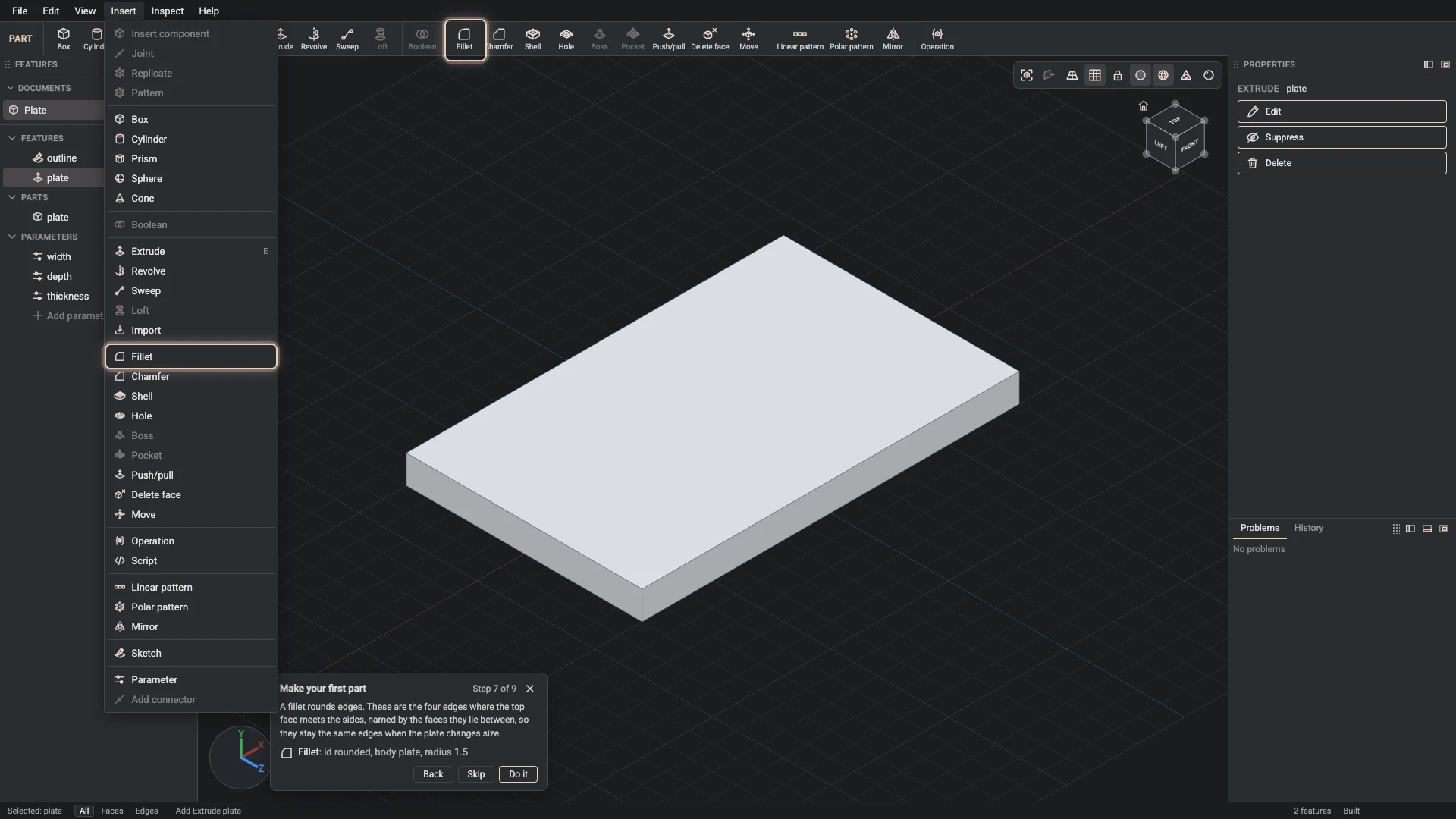
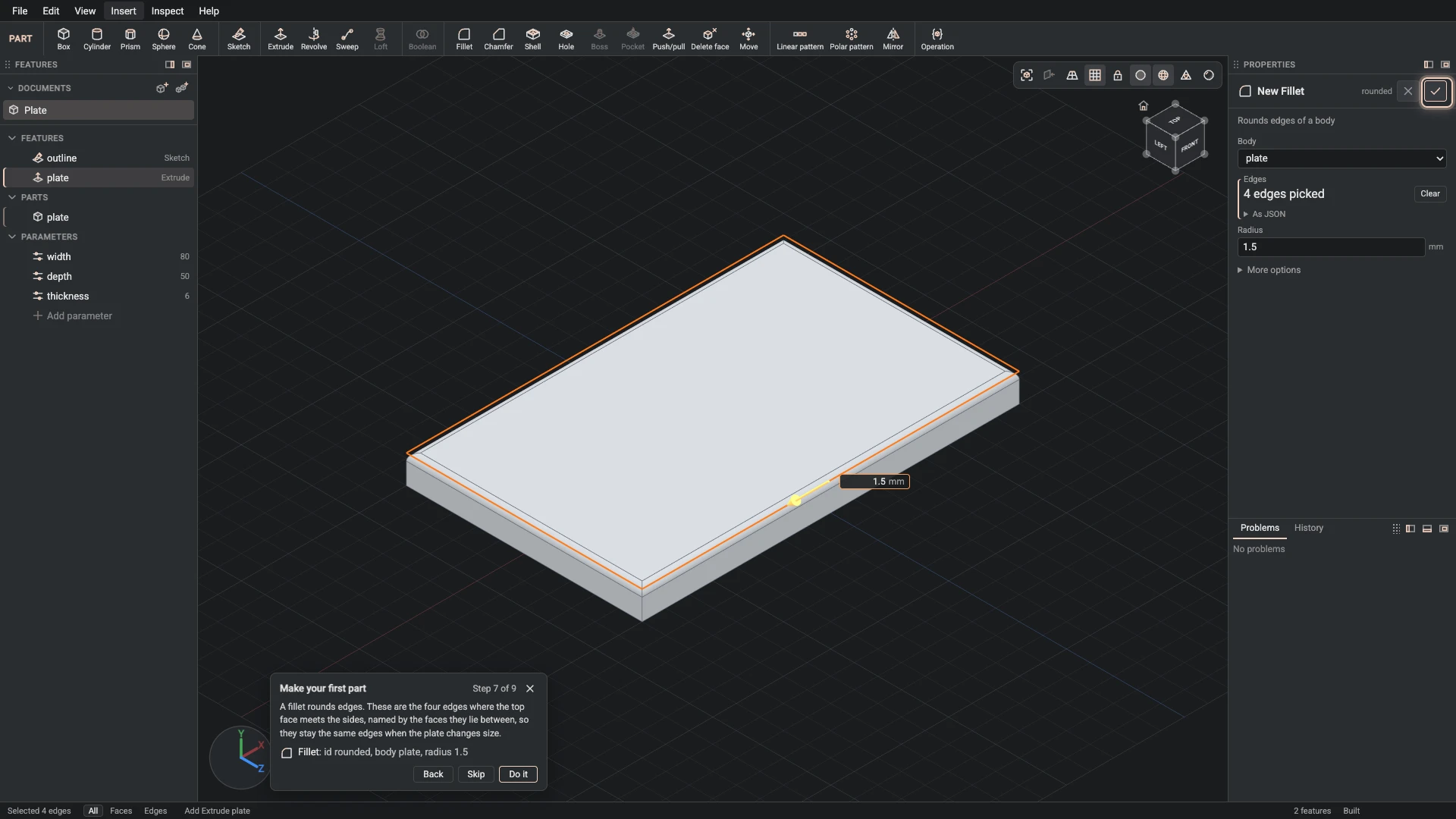
Fillet, from Insert > Fillet: id rounded, body plate, radius 1.5.
A fillet rounds edges. These are the four edges where the top face meets the sides, named by the faces they lie between, so they stay the same edges when the plate changes size.
-
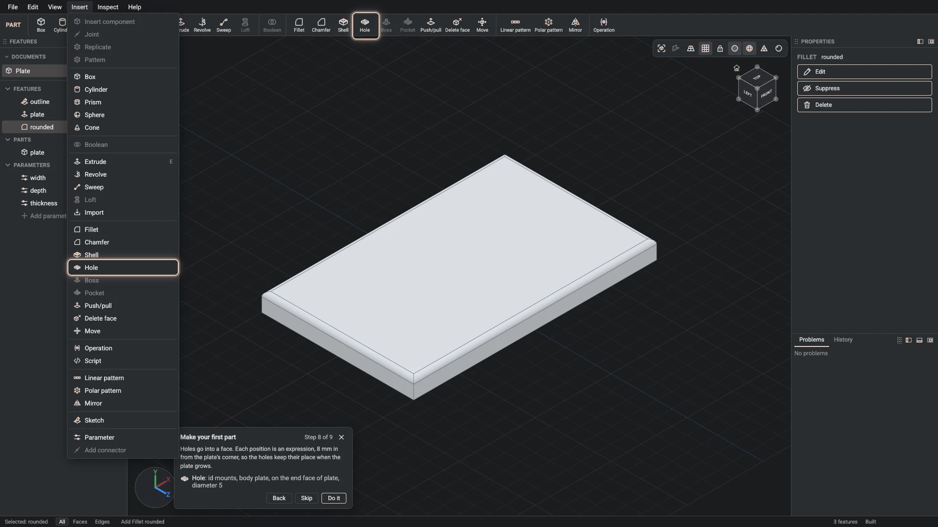
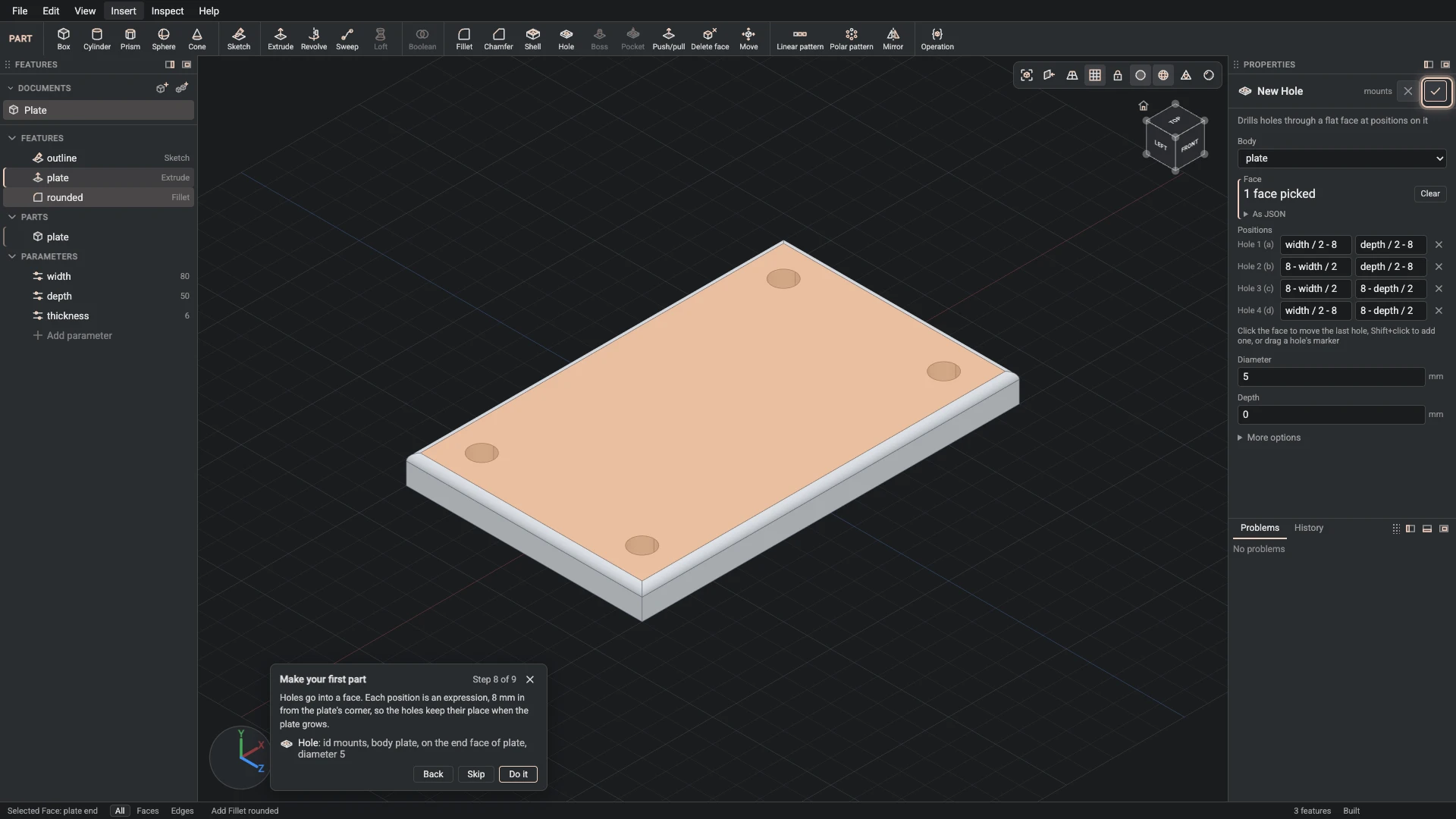
Hole, from Insert > Hole: id mounts, body plate, on the end face of plate, diameter 5.
Holes go into a face. Each position is an expression, 8 mm in from the plate's corner, so the holes keep their place when the plate grows.
Wider plate
-
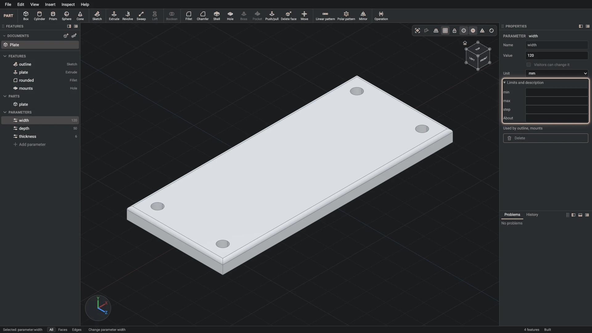
Change parameter, from the Properties panel: name width, value 120.
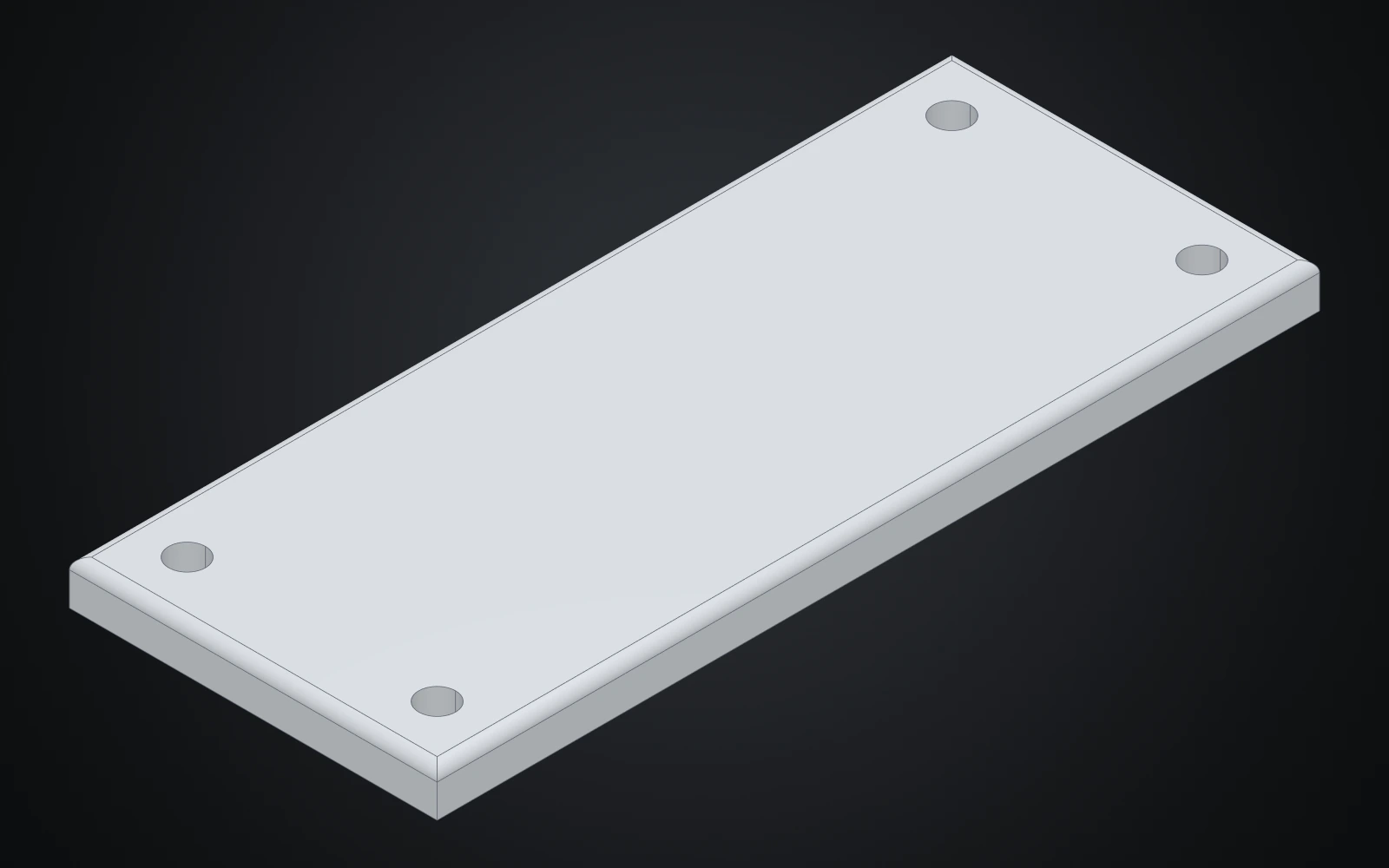
Now make the plate wider. The sketch, the extrude, the rounded edges and the holes all follow the new width.
What you made
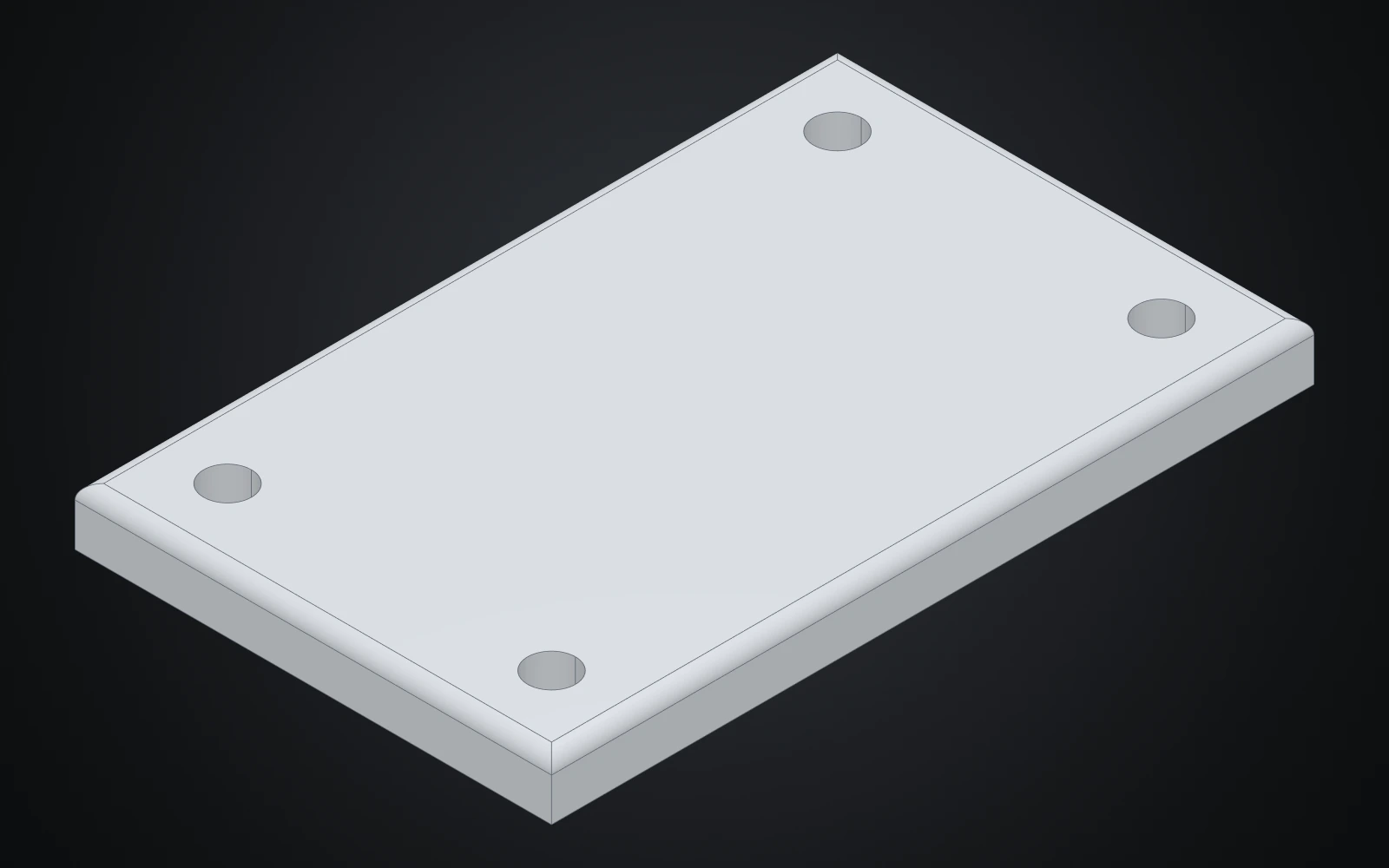
The plate is four features in the Features panel: the sketch outline, the extrude plate, the fillet rounded and the hole mounts. None of them holds a size of its own. The sketch's sides are width and depth, the extrude's distance is thickness, and each hole sits 8 mm in from a corner through an expression. That is why the last step only had to change width.
Two more things kept the plate right when it grew:
- The fillet names its edges by the faces they lie between, the top and the sides, not by a number that a changed model would shuffle.
- The holes sit on the face the extrude ends on, so they move with it.
How the Designer works explains both ideas.
Try next
- Select
thicknessin the Features panel and change its value in Properties. - Undo the last change with Ctrl+Z (⌘Z on macOS), and look at the History tab.
- Move on to Model a desk robot arm, where parts come together in an assembly.
Verified against the product in October 2026