A tour of the Designer
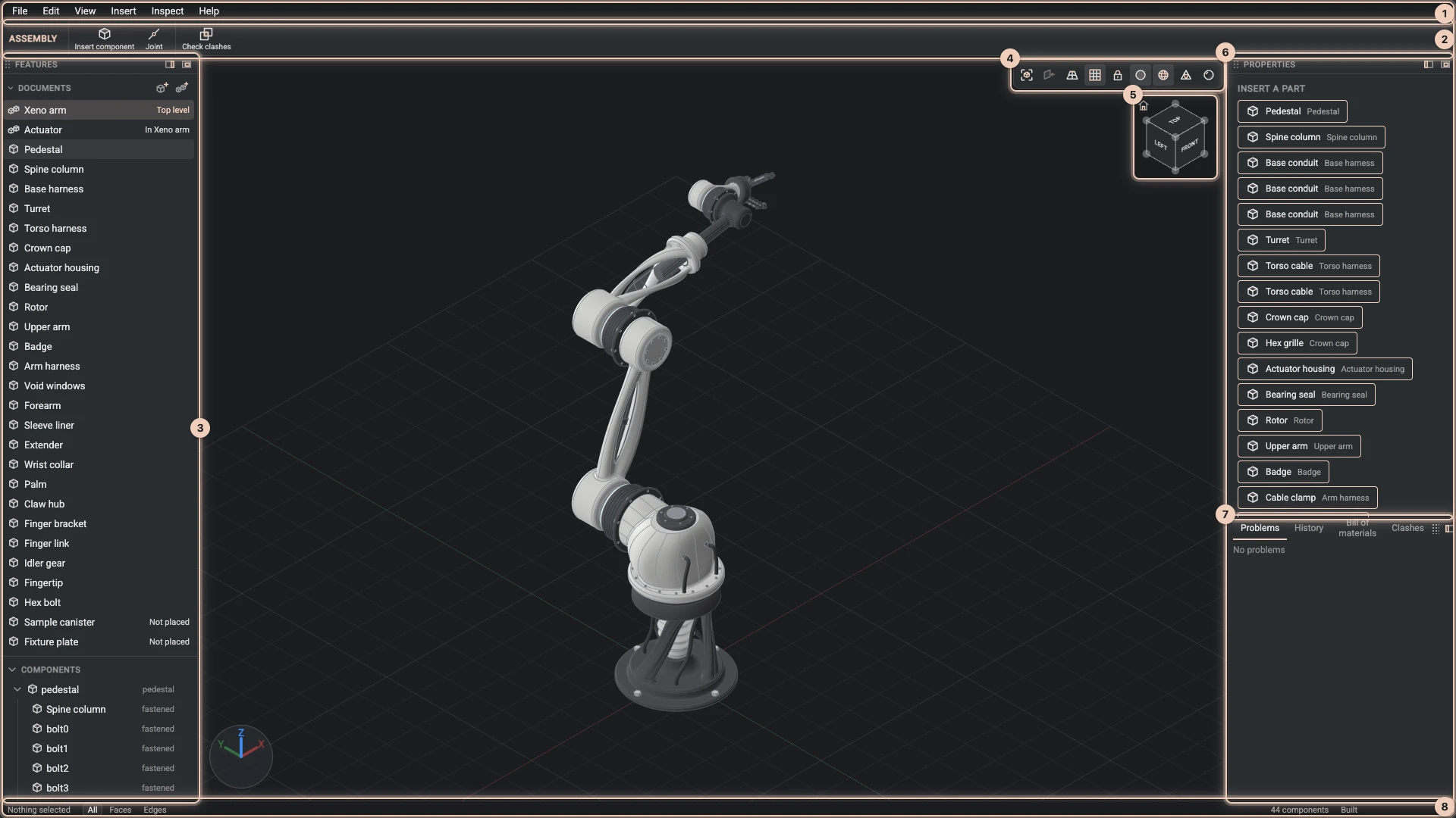
The numbers match the picture, which shows the robot arm from the showcases.
- The menus. File, Edit, View, Insert, Inspect and Help hold every command. A command that cannot run yet is greyed out, and its tip says why.
- The toolbar. The commands you use most. What does not fit the window folds into More.
- The Features panel. The project's documents at the top; under them, the open document's tree. A part lists its Parameters and its Features in the order they are built; an assembly lists its Components, Joints and Configurations. Right-click a row to edit, suppress, delete or roll back to it.
- The view bar. Fit all, Look at, Perspective, Show or hide the grid and Lock rotation, and how the model is drawn: Faces, Edges, Triangles and Realistic.
- The view cube. Click a face, an edge or a corner to look from there.
- The Properties panel. What you selected: a feature, a parameter, a part with its material and mass, a component or a joint.
- The dock. Problems lists what a build could not do and History the changes of this session. An assembly adds Bill of materials and Clashes, and Review appears when an agent has changed something.
- The status bar. What the pointer is over, whether a click picks faces, edges or both (keys 1, 2 and 3), the progress of a long build, and whether an agent is working.
Each panel can dock on either side or float: use its placement buttons, or drag it by its grip. Drag the edges between panels to resize them. The Designer remembers the layout in this browser.
Select, then change
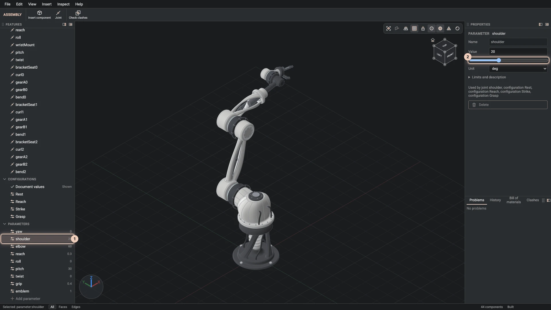
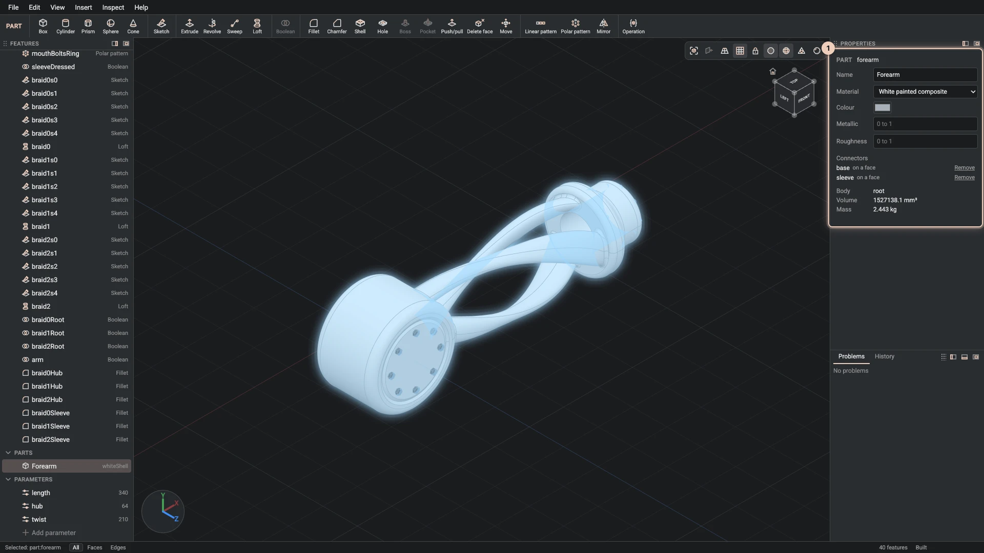
Click a row of the tree or a face in the view, and Properties shows it. A parameter has a value and a slider: drag it and the part rebuilds as you go. A part has its name, material and colour, with the volume and mass worked out.
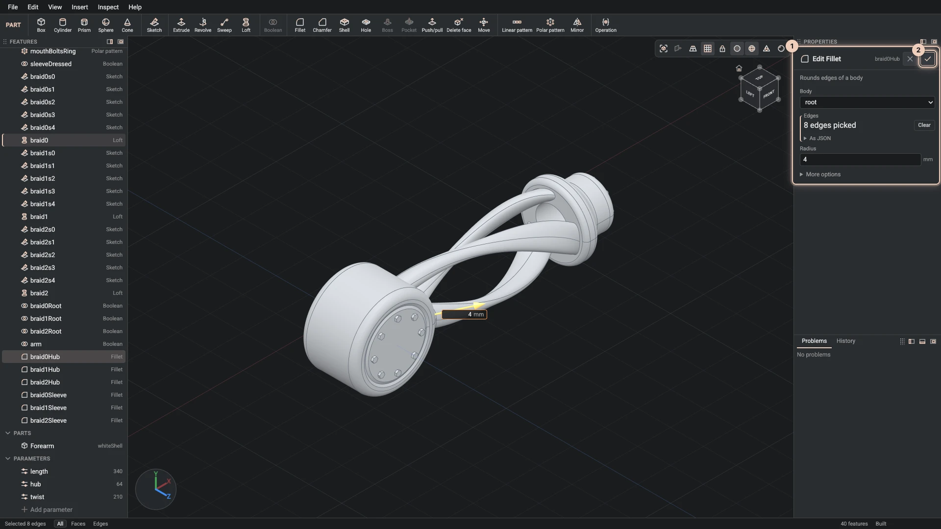
To change a feature, right-click it and choose Edit feature. Its dialog opens as you left it, the view shows handles to drag, and OK rebuilds everything after it.
Assemblies at a glance
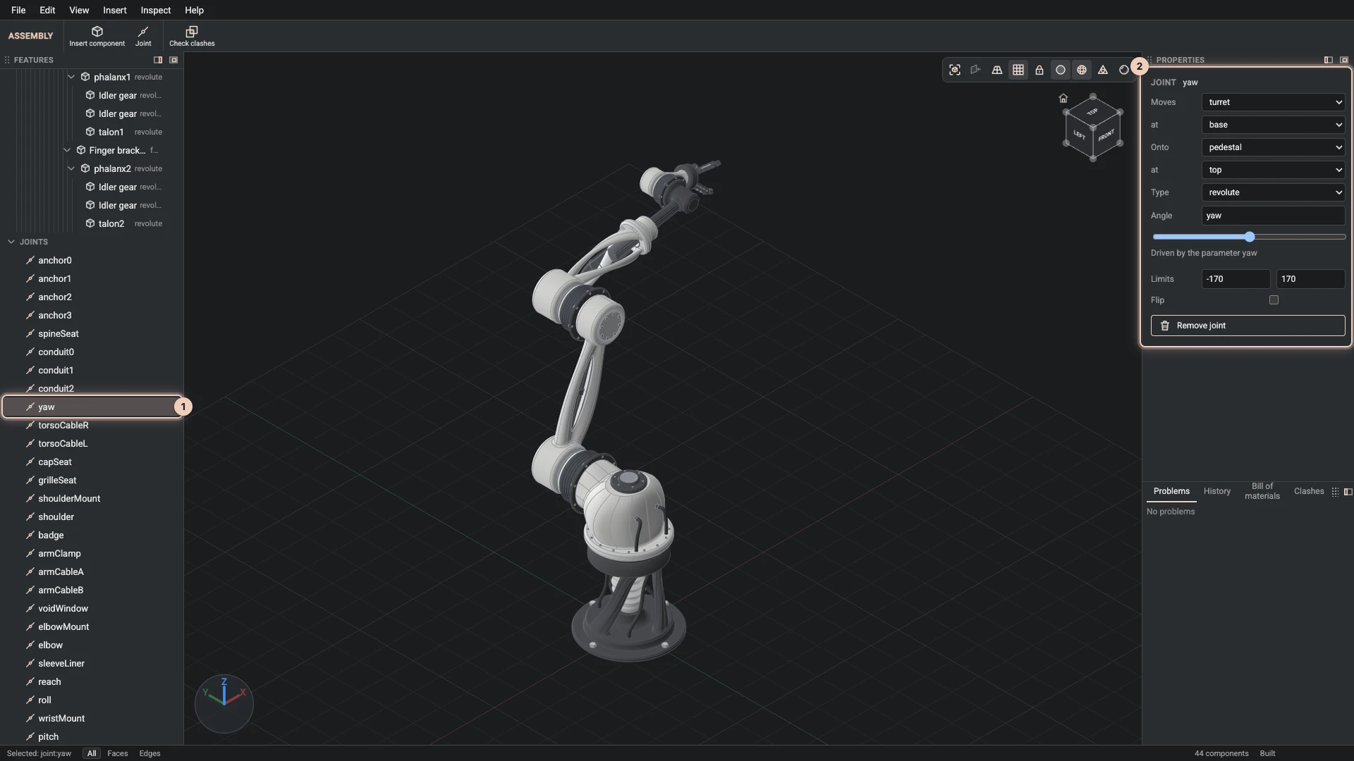
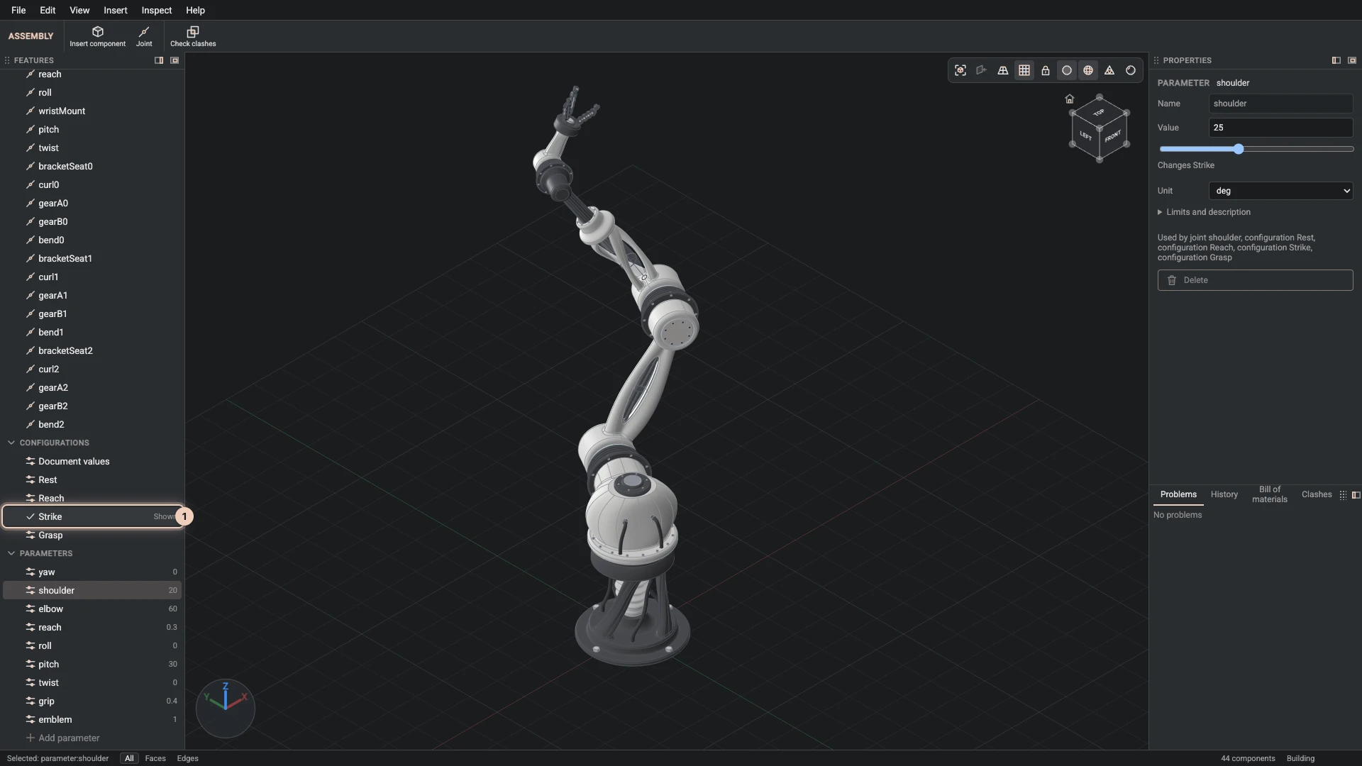
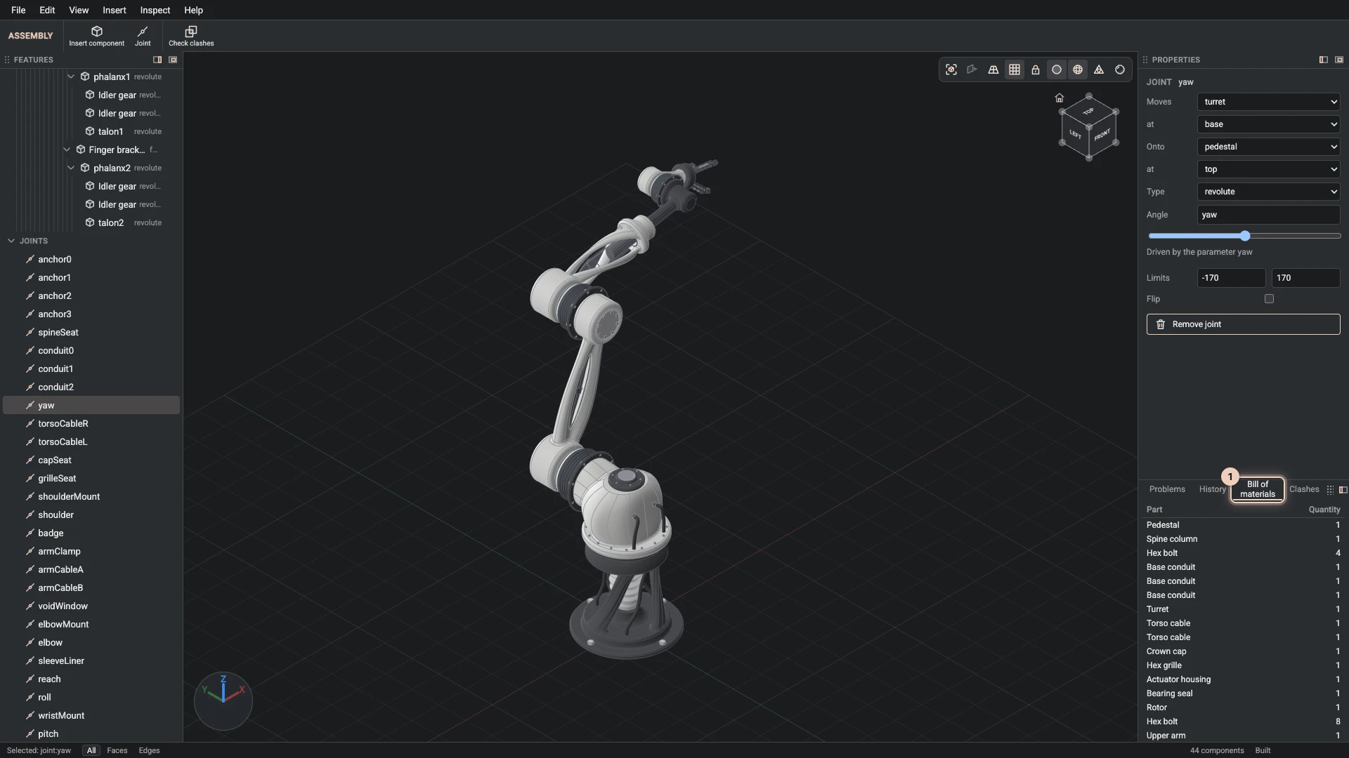
Select a joint to see what it joins and how far it may move. A configuration poses the whole assembly at once, and the bill of materials counts every part it places.
How the model is drawn
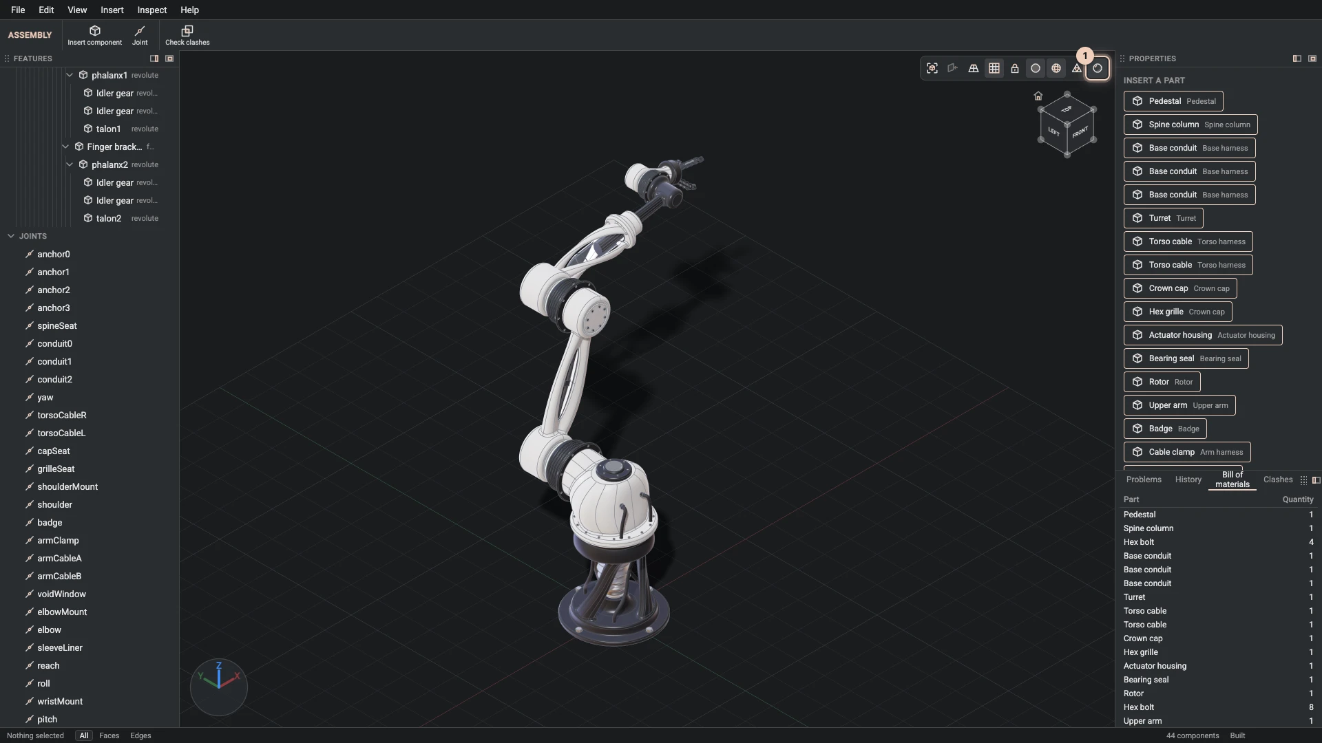
Realistic lights the parts as their materials look, with reflections and soft shadows; off, the view is the matte CAD look that is easier to model in. Edges draws the edges in either.
Find a command
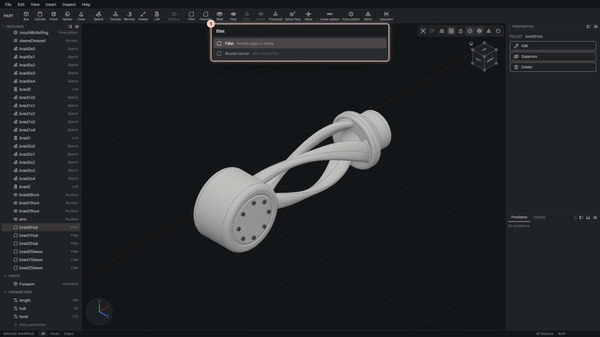
Find a command (Ctrl+K, ⌘K on macOS) lists every command that matches what you type, with its key, and runs the one you choose.
Learn by doing
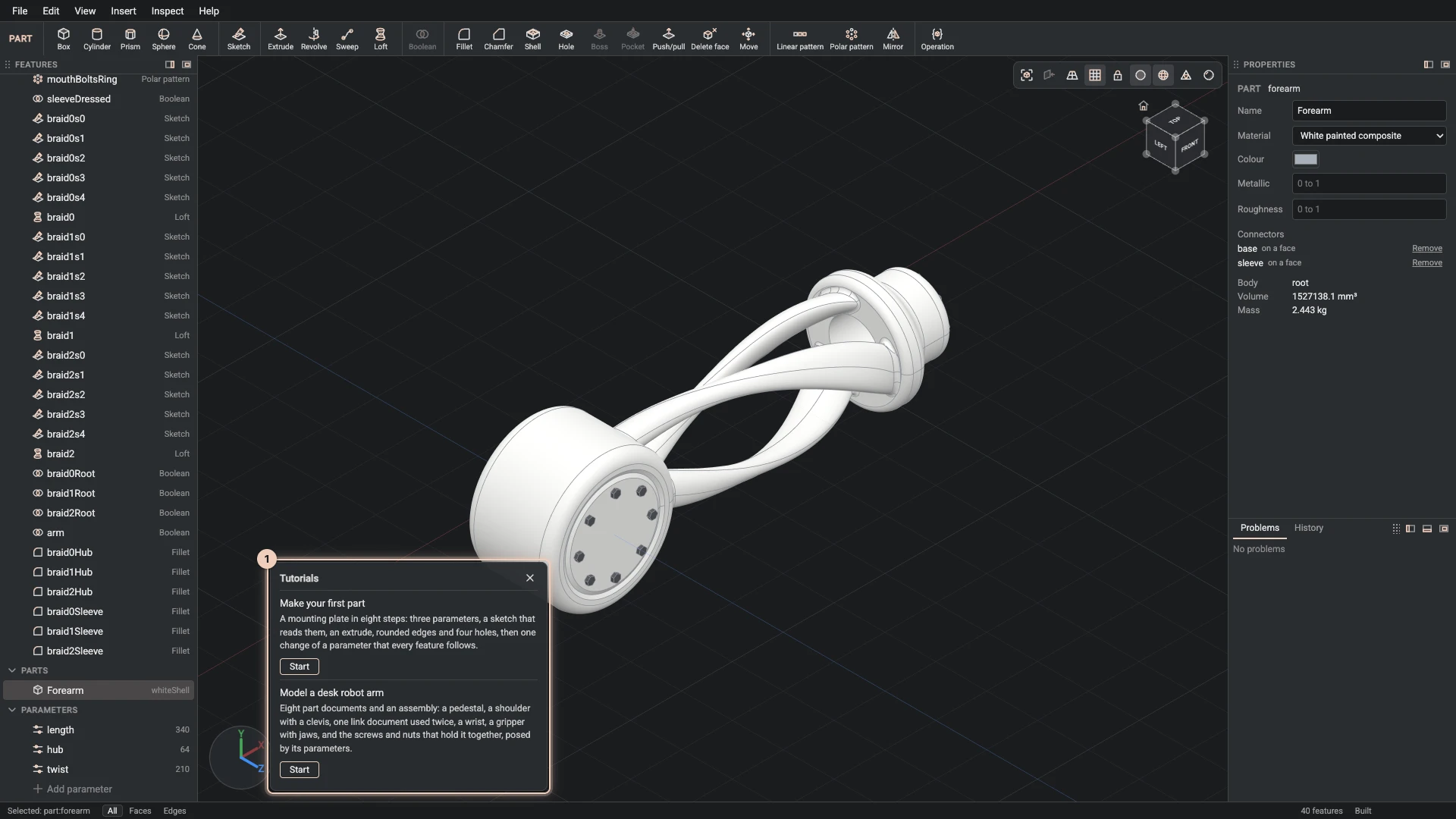
Help > Tutorials plays a tutorial in the Designer, step by step. Make your first part is the place to start.
Verified against the product in October 2026