Model a desk robot arm: the assembly
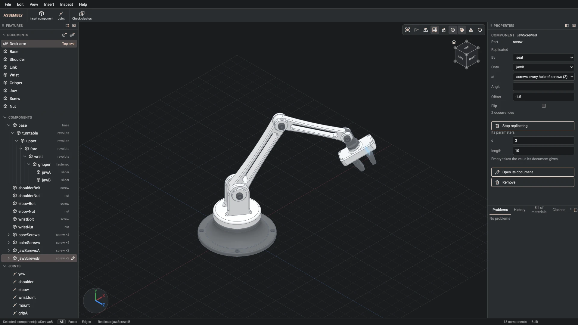
The assembly puts the eight parts together. Its parameters drive the joints, so posing the arm is changing a number, and the fasteners are replicated onto connectors, so each lands on every hole it belongs in.
Each step shows the Designer as you make it: a feature's dialog filled in with the step's values, with the tutorial card ringing OK, or what the step made. The first time a command appears, a picture shows where it is. The step numbers match the card's in Help > Tutorials.
-
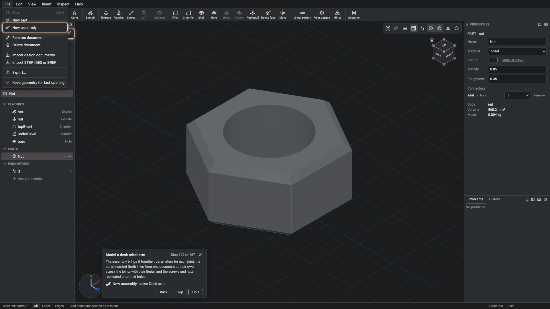
New assembly, from File > New assembly: name Desk arm.
The assembly brings it together: parameters for each joint, the parts inserted (both links from one document at their own sizes), the joints with their limits, and the screws and nuts replicated onto their holes.

-
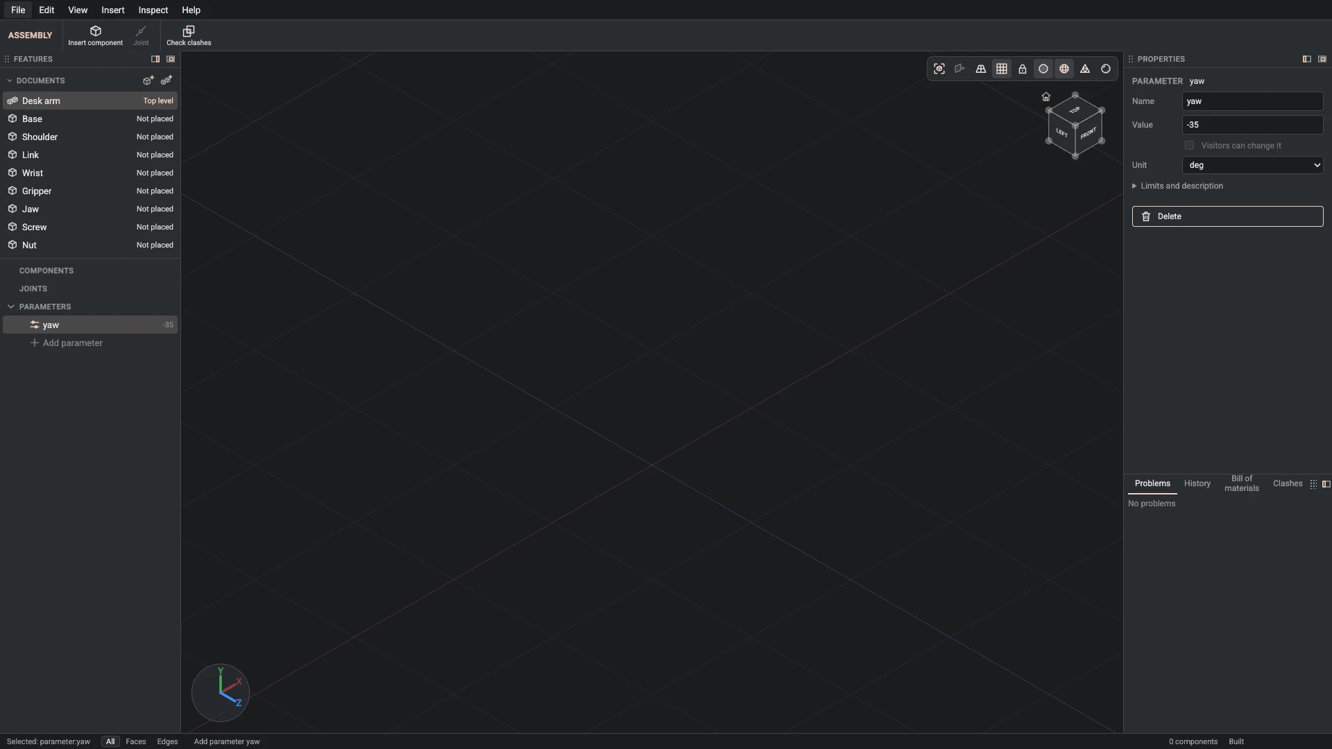
Parameter, from Insert > Parameter: name yaw, value -35, unit deg.
Add the parameter yaw, -35 degrees: how far the shoulder turns on the base.
-
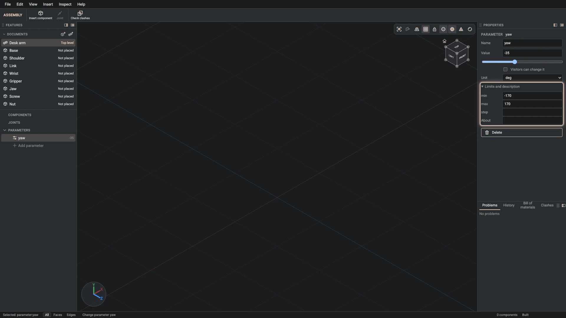
Change parameter, from the Properties panel: name yaw, min -170, max 170.
Give yaw its range, -170 to 170 degrees: the values the design is drawn for.
-
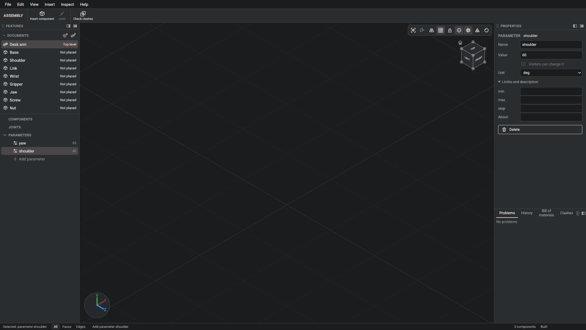
Parameter, from Insert > Parameter: name shoulder, value 60, unit deg.
Add the parameter shoulder, 60 degrees: the upper link's angle at the shoulder.
-
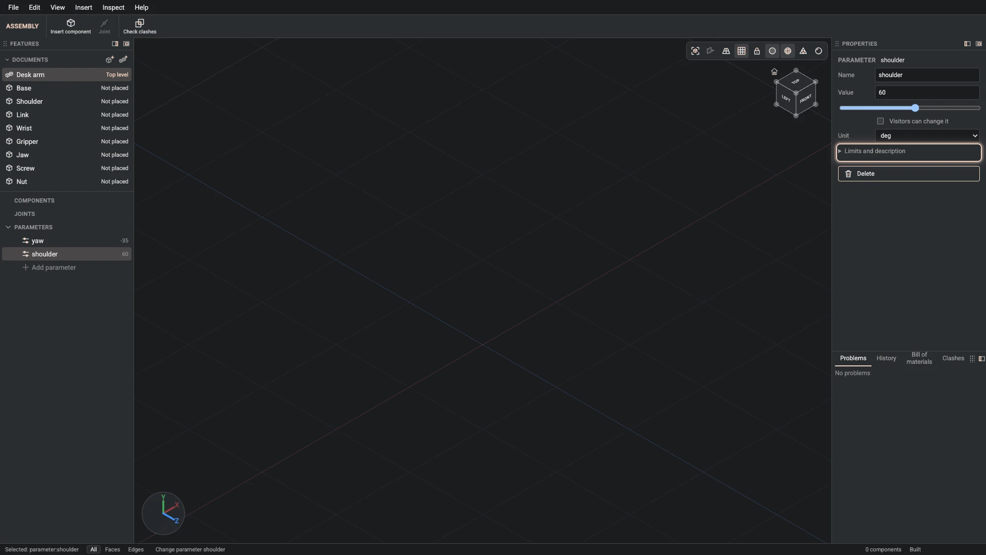
Change parameter, from the Properties panel: name shoulder, min -10, max 120.
Give shoulder its range, -10 to 120 degrees: the values the design is drawn for.
-
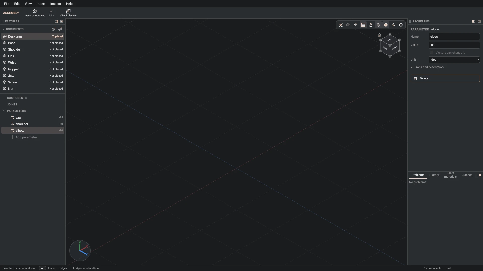
Parameter, from Insert > Parameter: name elbow, value -80, unit deg.
Add the parameter elbow, -80 degrees: the forearm's angle at the elbow.
-
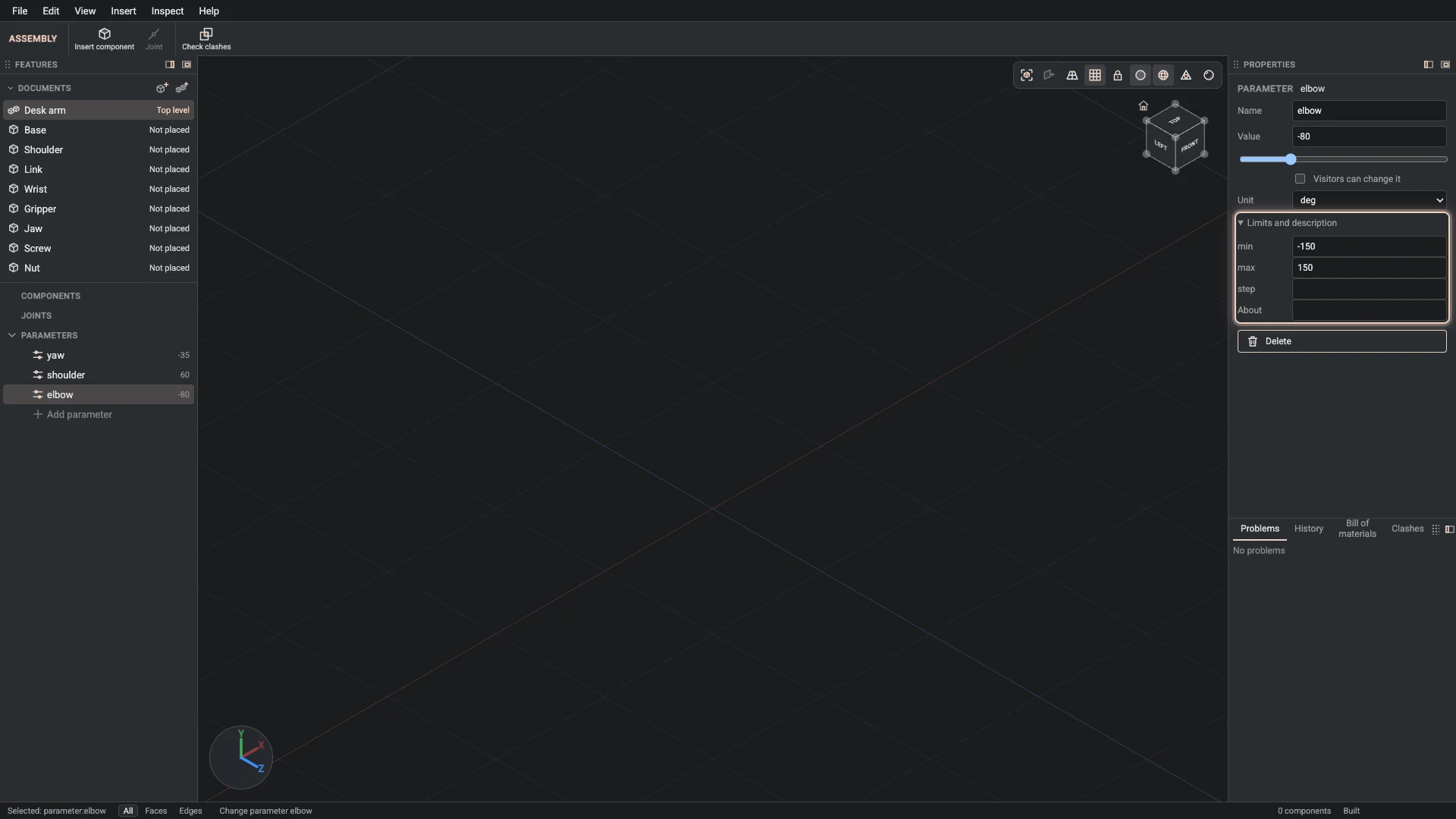
Change parameter, from the Properties panel: name elbow, min -150, max 150.
Give elbow its range, -150 to 150 degrees: the values the design is drawn for.
-
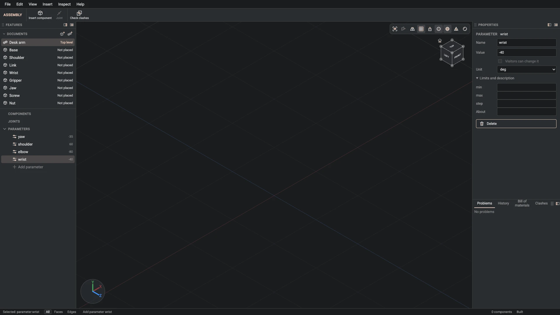
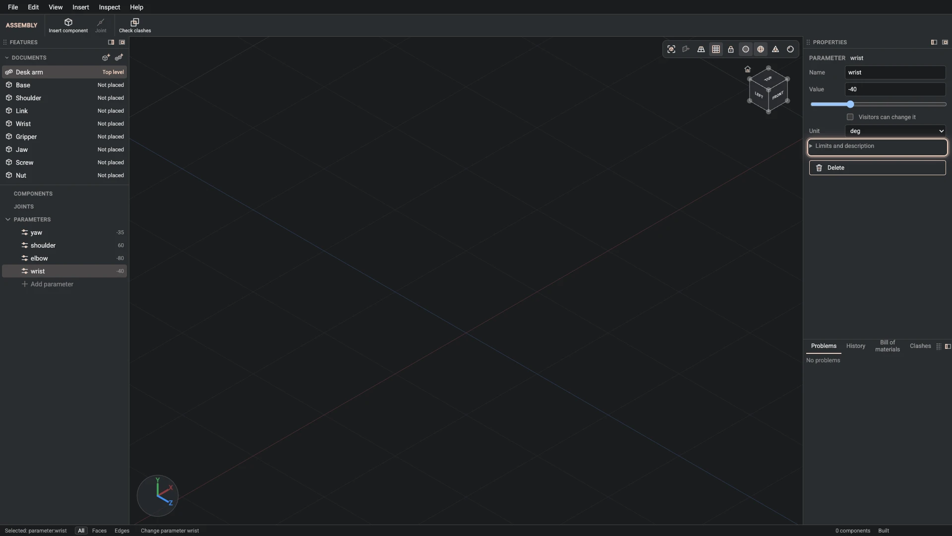
Parameter, from Insert > Parameter: name wrist, value -40, unit deg.
Add the parameter wrist, -40 degrees: the wrist's angle.
-
Change parameter, from the Properties panel: name wrist, min -90, max 90.
Give wrist its range, -90 to 90 degrees: the values the design is drawn for.
-
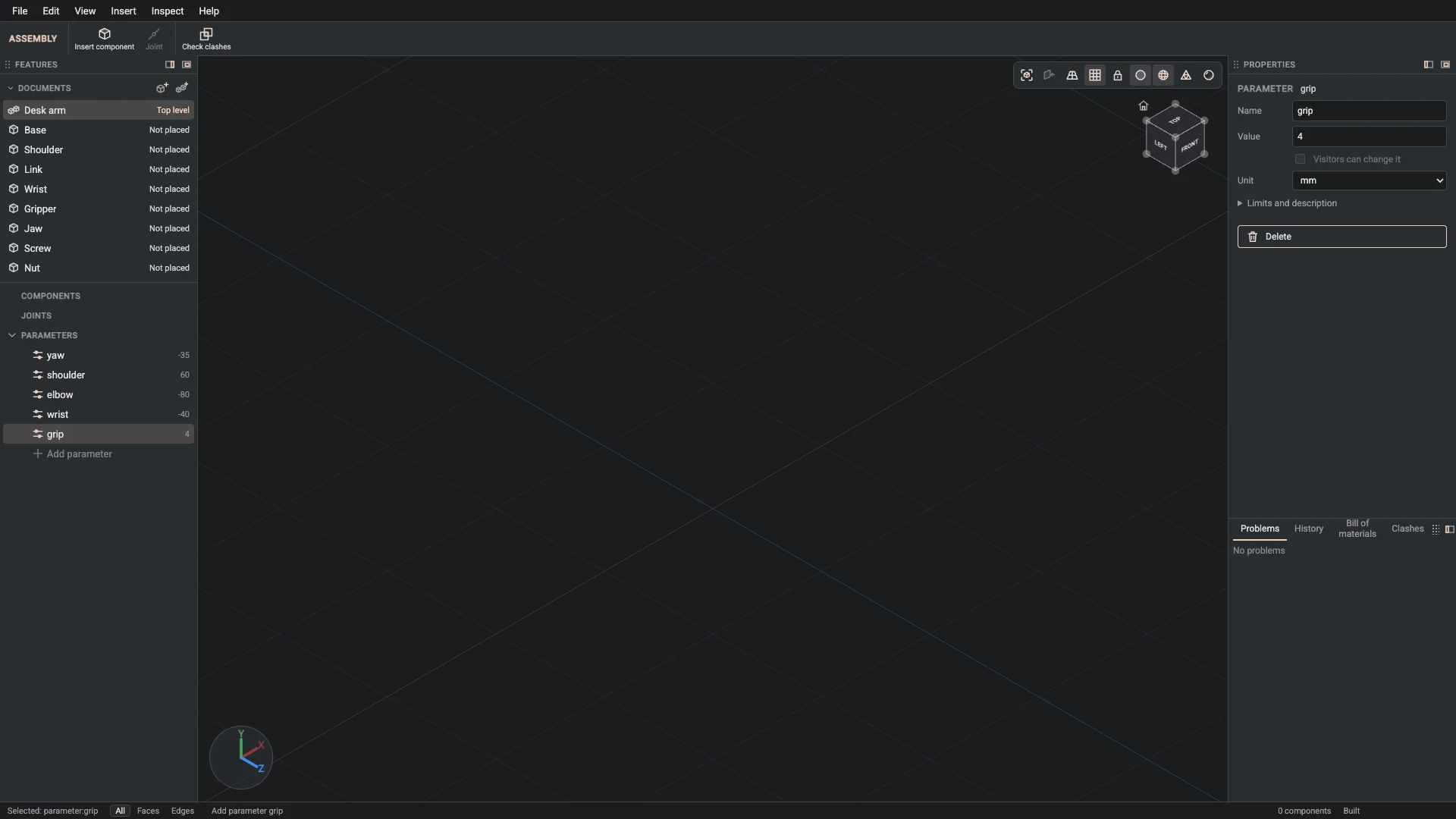
Parameter, from Insert > Parameter: name grip, value 4, unit mm.
Add the parameter grip, 4 mm: how far each jaw slides open.
-
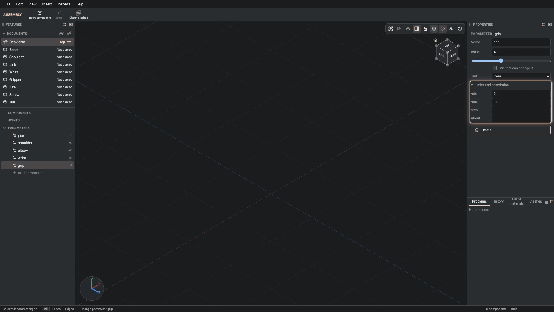
Change parameter, from the Properties panel: name grip, min 0, max 11.
Give grip its range, 0 to 11 mm: the values the design is drawn for.
-
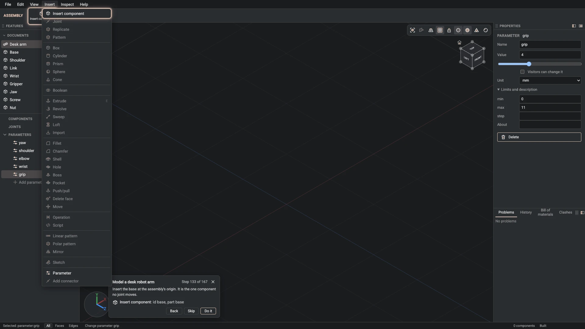
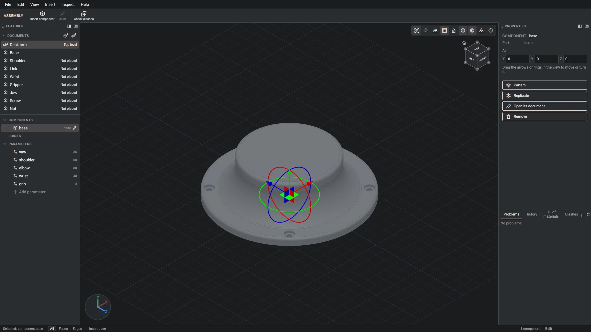
Insert component, from Insert > Insert component: id base, part base.
Insert the base at the assembly's origin. It is the one component no joint moves.
-
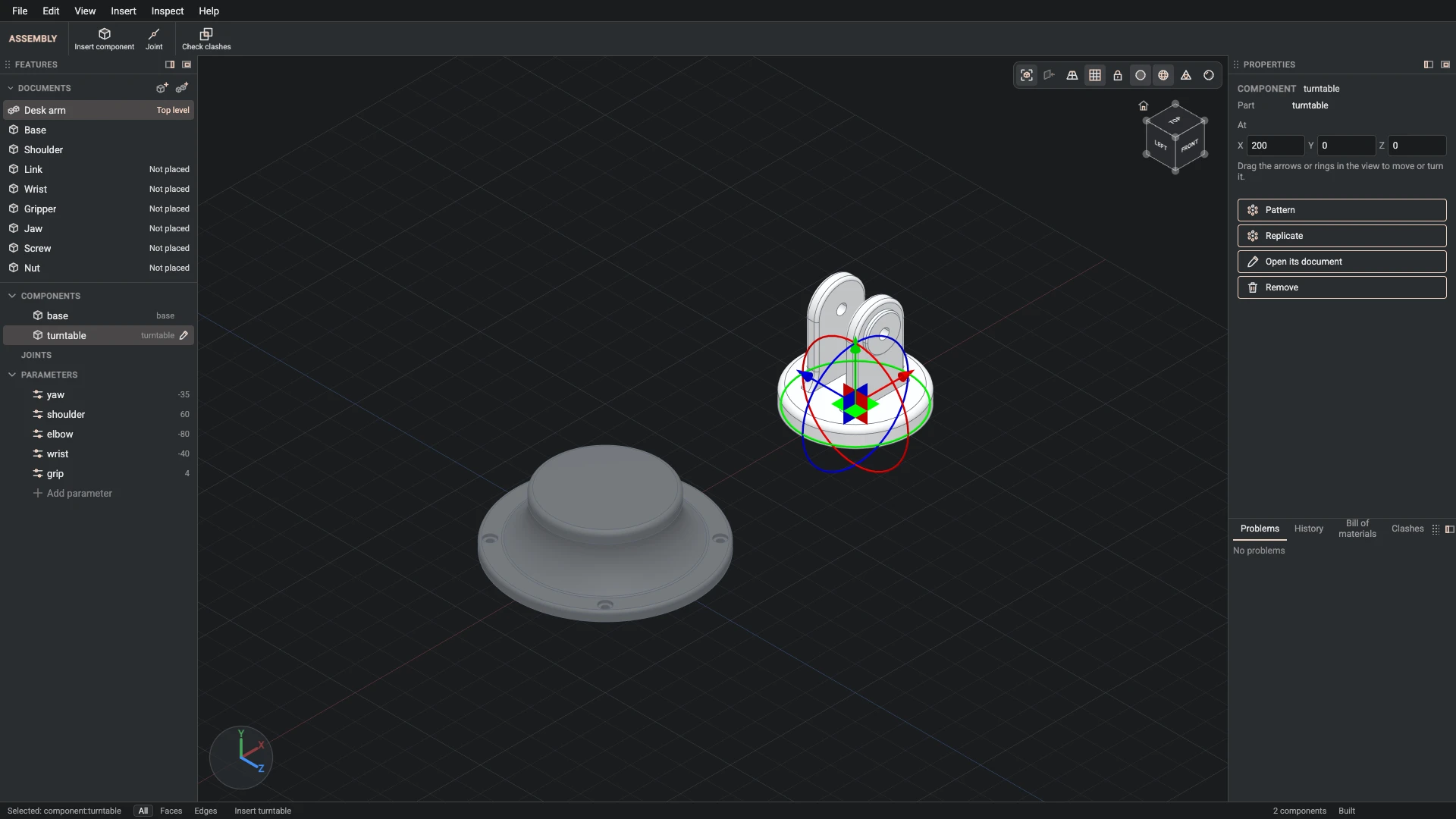
Insert component, from Insert > Insert component: id turntable, part turntable.
Insert the shoulder. Where it lands does not matter: the joint in the next step places it.
-
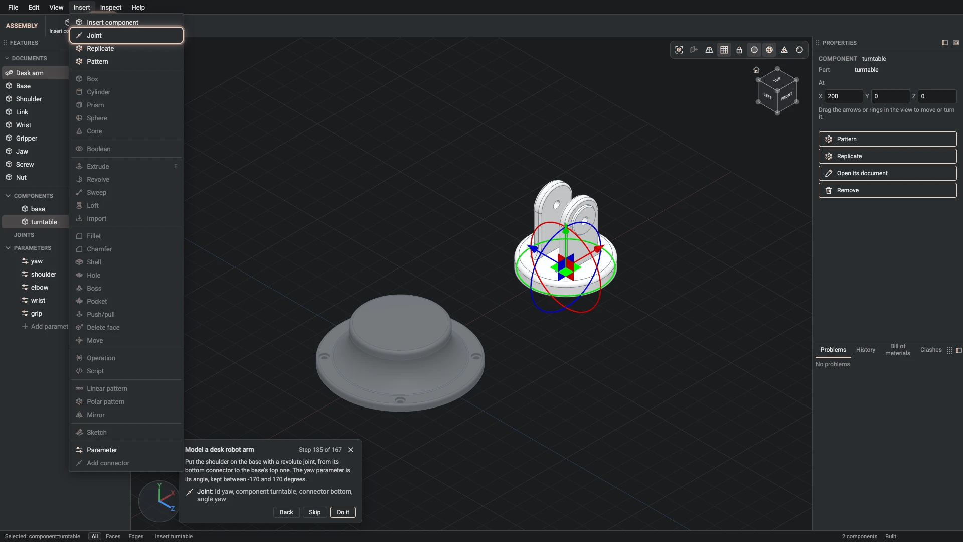
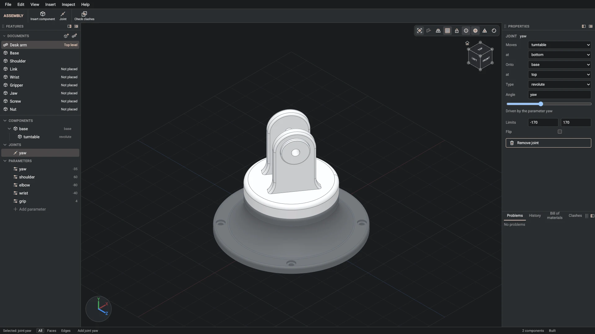
Joint, from Insert > Joint: id yaw, component turntable, connector bottom, angle yaw.
Put the shoulder on the base with a revolute joint, from its bottom connector to the base's top one. The yaw parameter is its angle, kept between -170 and 170 degrees.
-
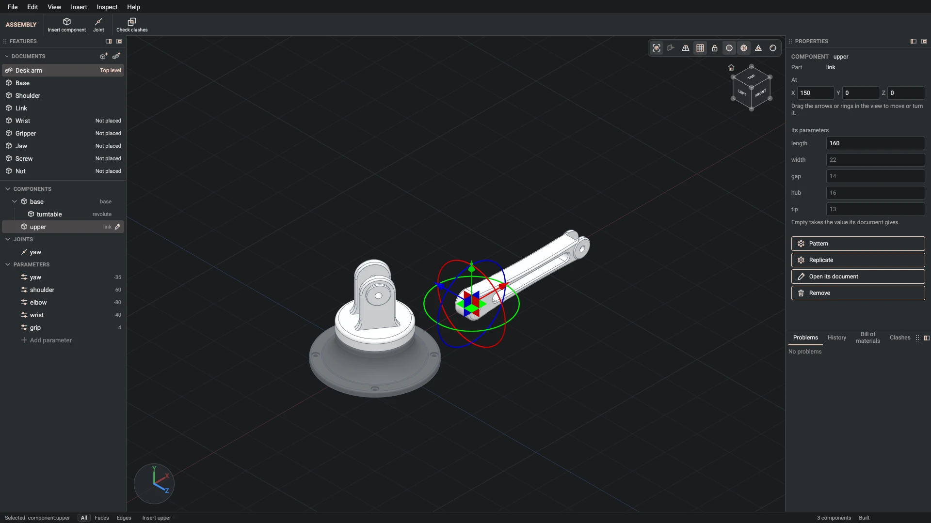
Insert component, from Insert > Insert component: id upper, part link.
Insert the link as the upper arm, 160 mm between its pivots.
-
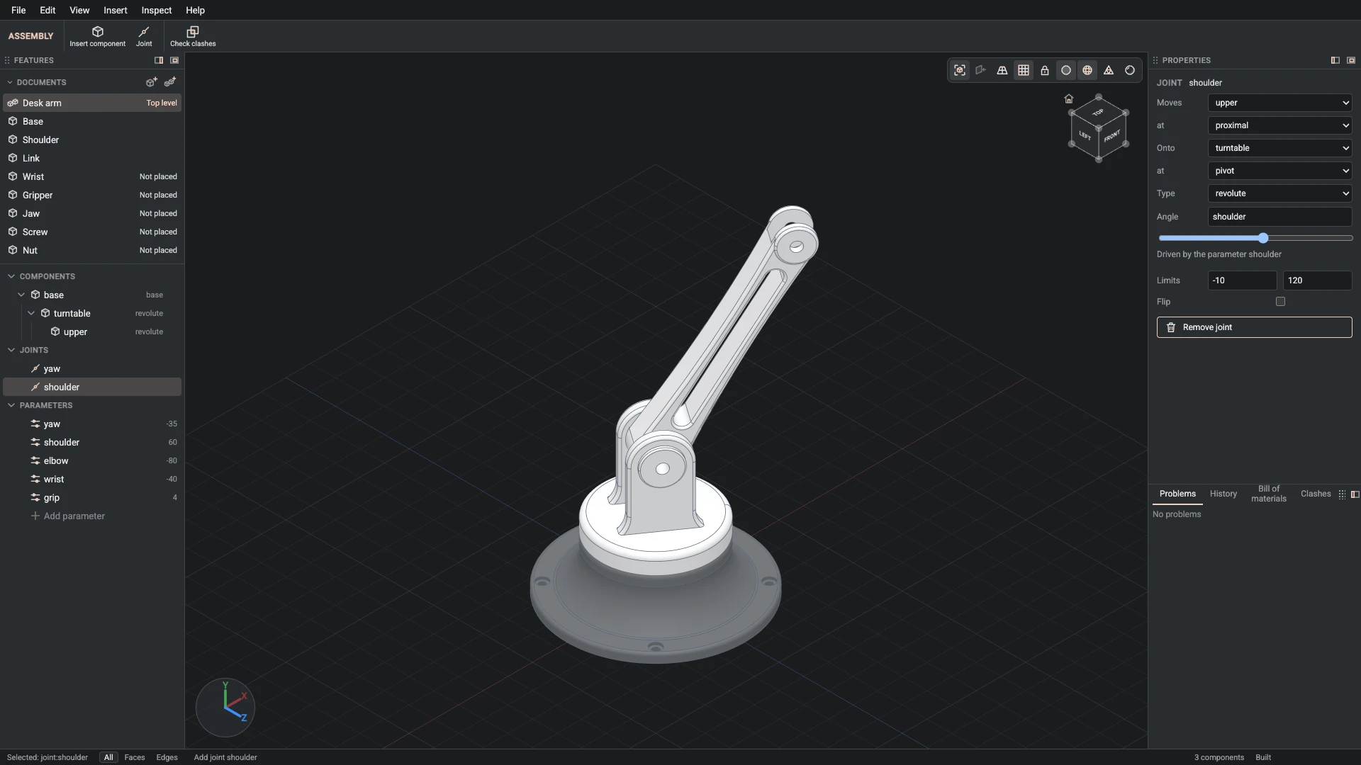
Joint, from Insert > Joint: id shoulder, component upper, connector proximal, angle shoulder.
Join the upper link's near end to the shoulder's pivot with a revolute joint, turned by shoulder.
-
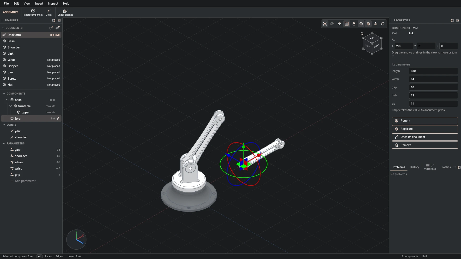
Insert component, from Insert > Insert component: id fore, part link.
Insert the same link document again as the forearm, slimmer and shorter: length 130, width 14, gap 10, hub 13, tip 11. One document, two parts.
-
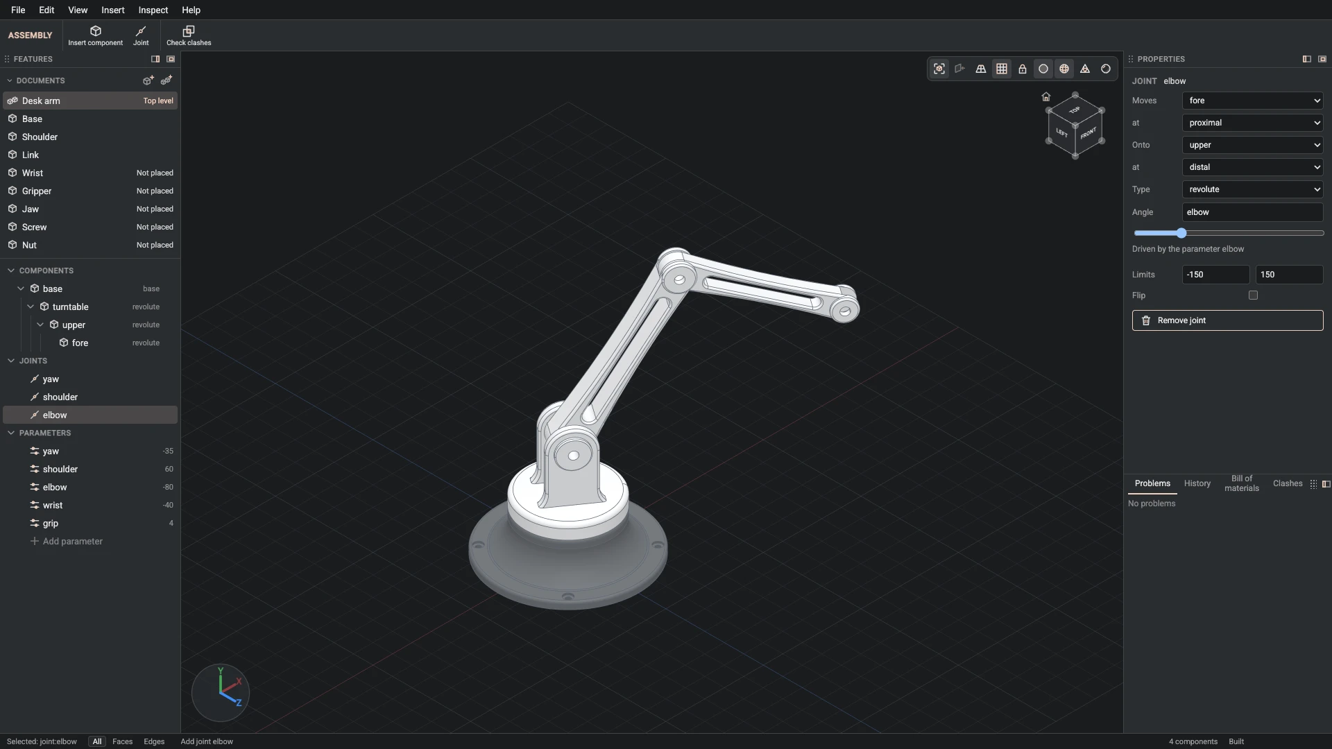
Joint, from Insert > Joint: id elbow, component fore, connector proximal, angle elbow.
Join the forearm's near end to the upper link's far end, turned by elbow.
-
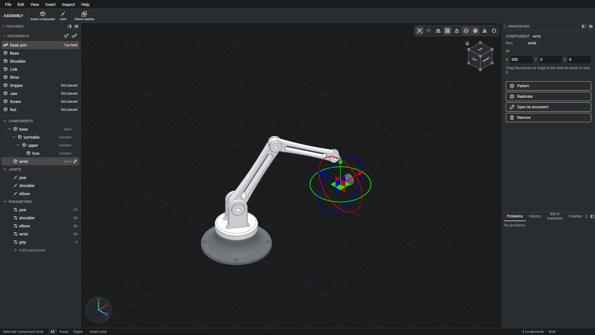
Insert component, from Insert > Insert component: id wrist, part wrist.
Insert the wrist.
-
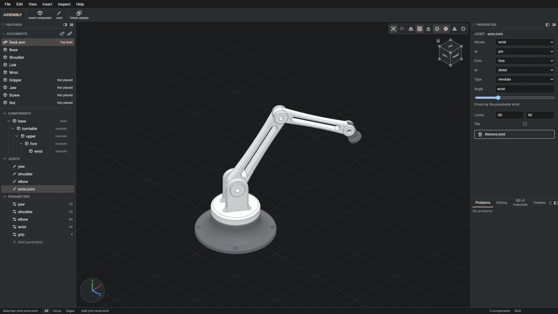
Joint, from Insert > Joint: id wristJoint, component wrist, connector pin, angle wrist.
Join the wrist into the forearm's fork, turned by wrist.
-
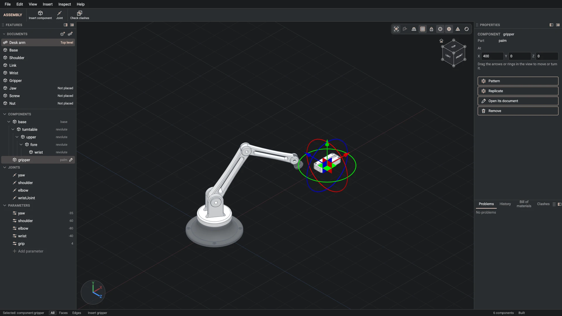
Insert component, from Insert > Insert component: id gripper, part palm.
Insert the gripper.
-
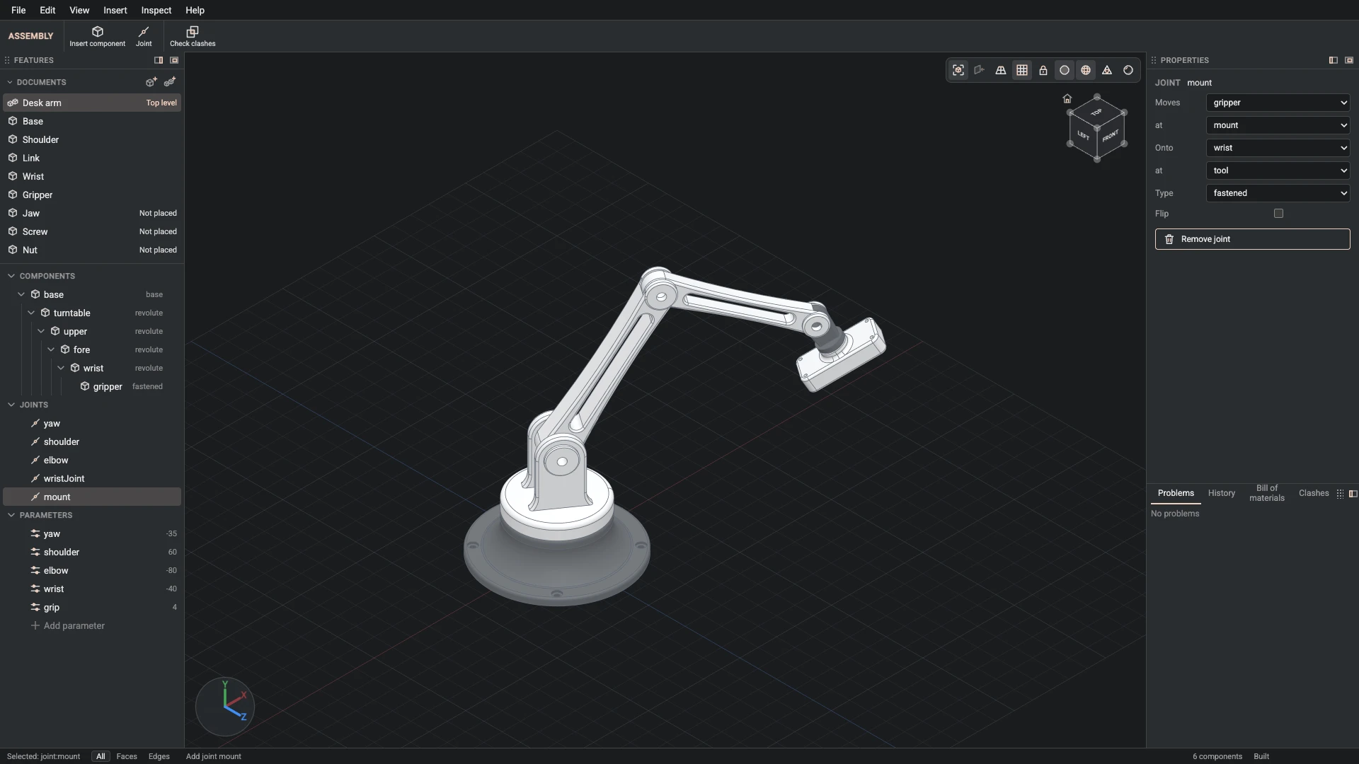
Joint, from Insert > Joint: id mount, component gripper, connector mount.
Fasten the gripper to the wrist's flange. A fastened joint holds it still.
-
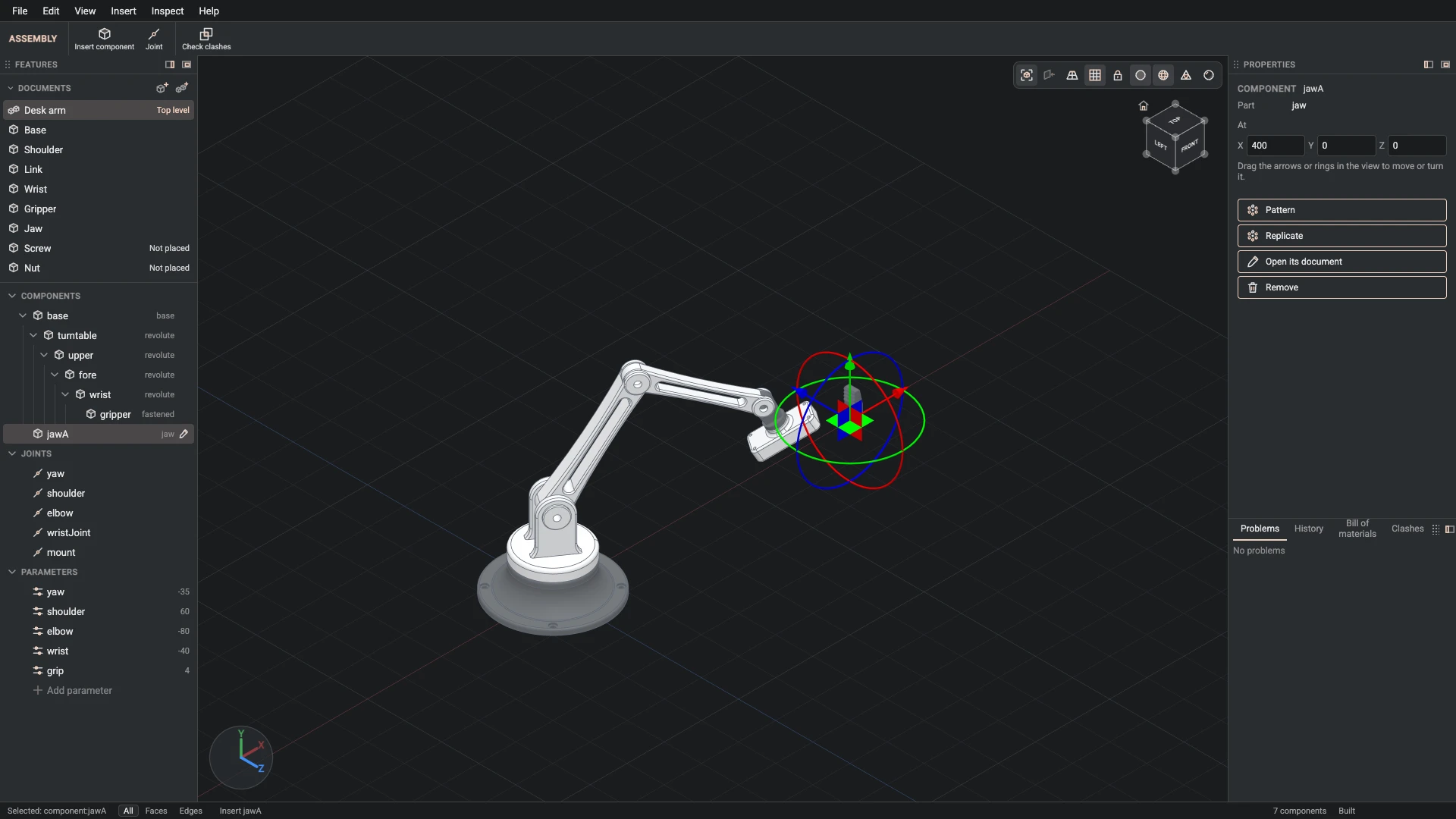
Insert component, from Insert > Insert component: id jawA, part jaw.
Insert a jaw.
-
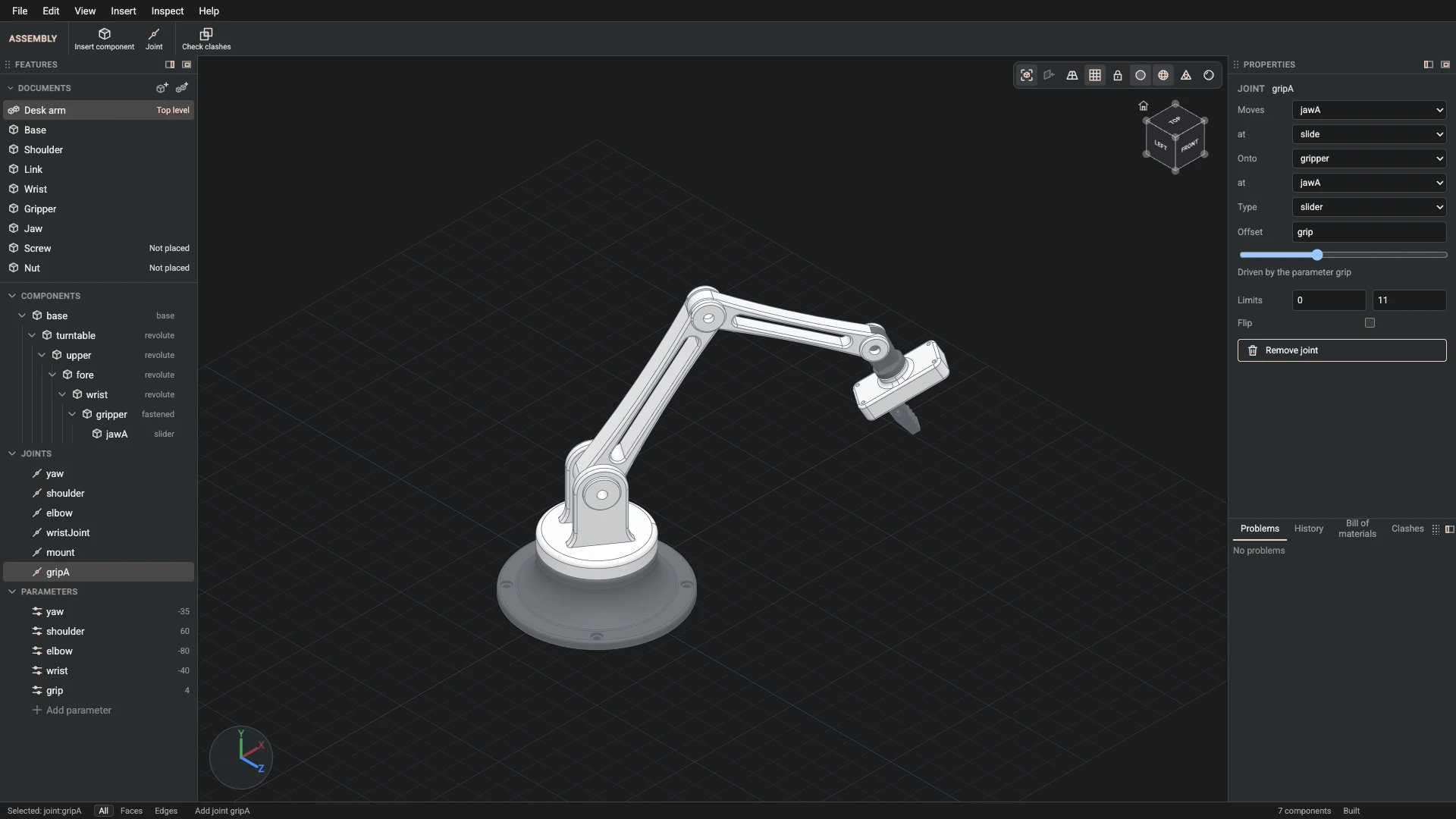
Joint, from Insert > Joint: id gripA, component jawA, connector slide, offset grip.
Put the first jaw in its rail with a slider joint. Its offset is the grip parameter, 0 to 11 mm.
-
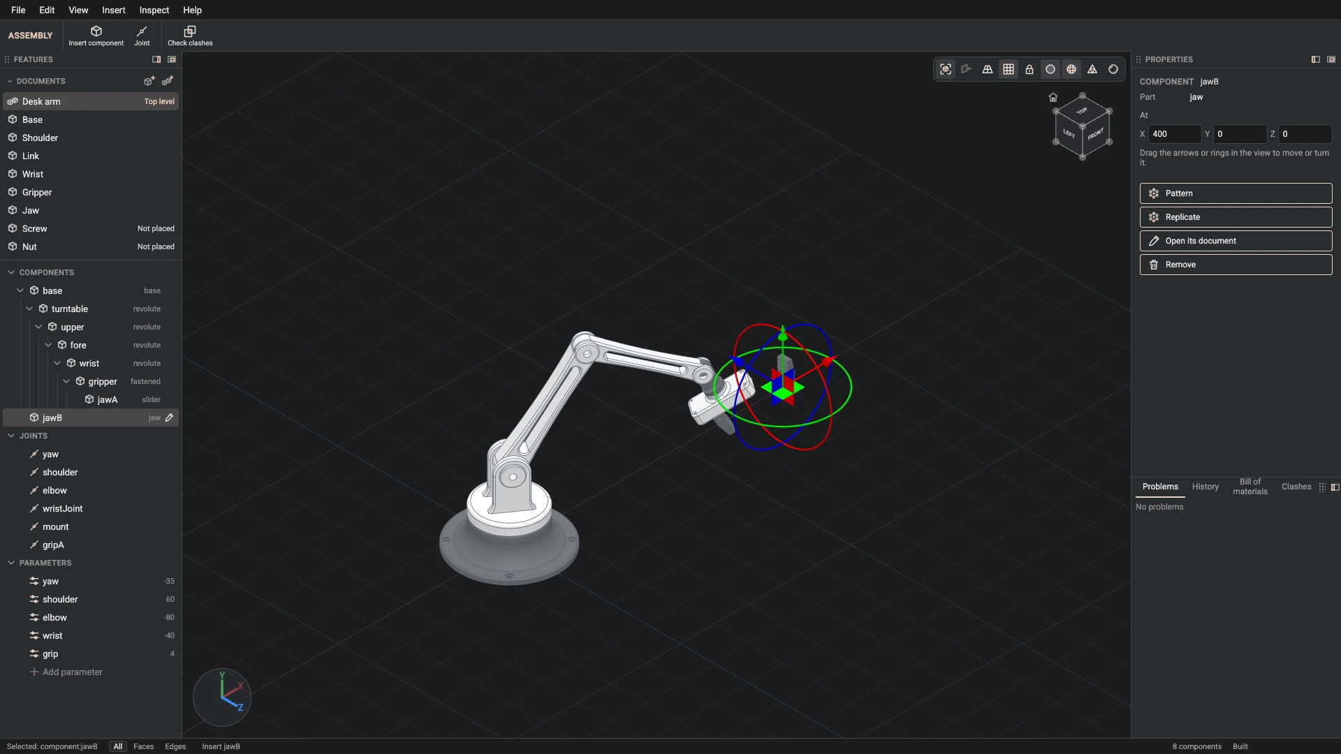
Insert component, from Insert > Insert component: id jawB, part jaw.
Insert a second jaw from the same document.
-
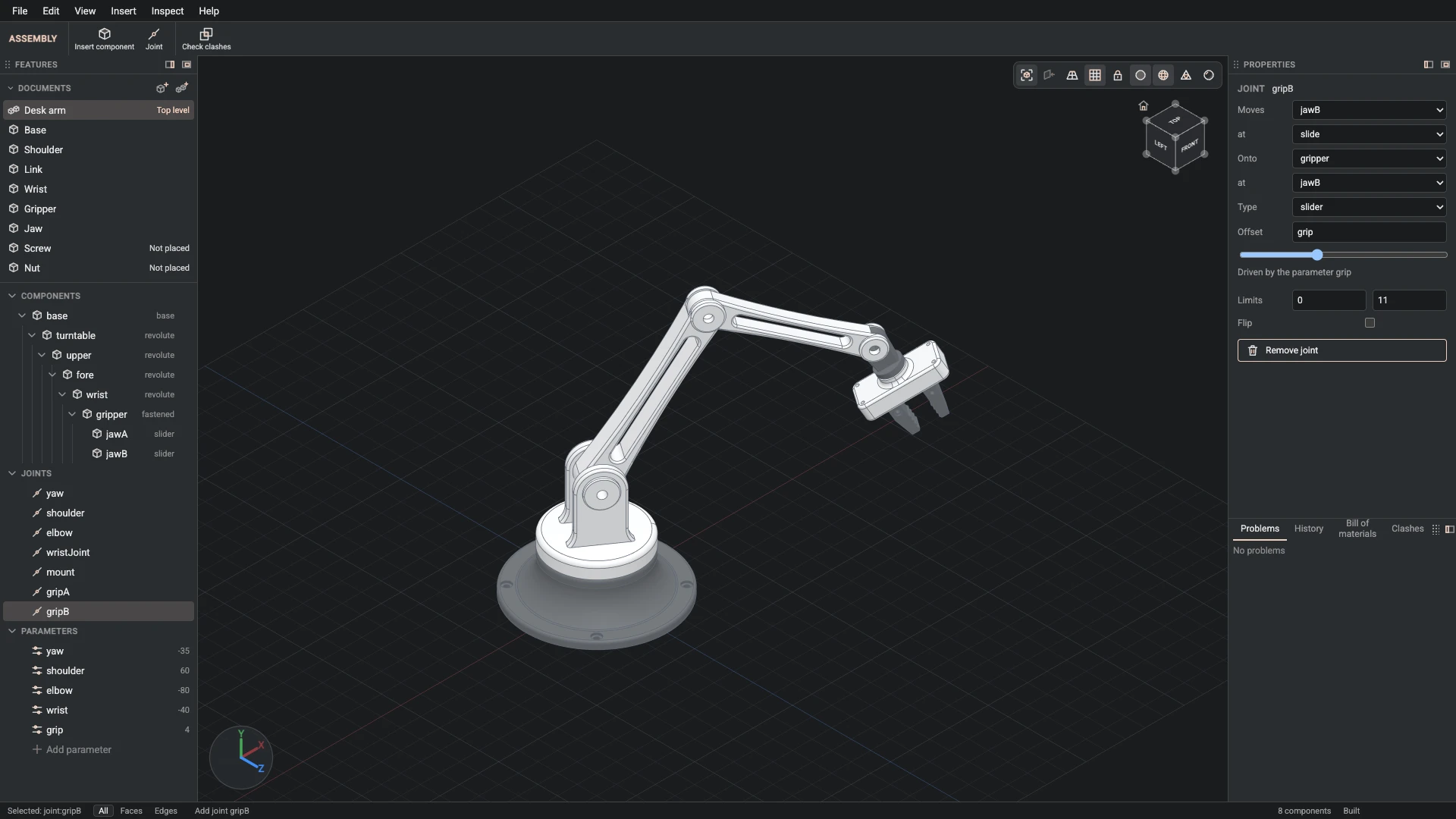
Joint, from Insert > Joint: id gripB, component jawB, connector slide, offset grip.
Put the second jaw in the other rail, driven by the same grip, so both jaws open and close together.
-
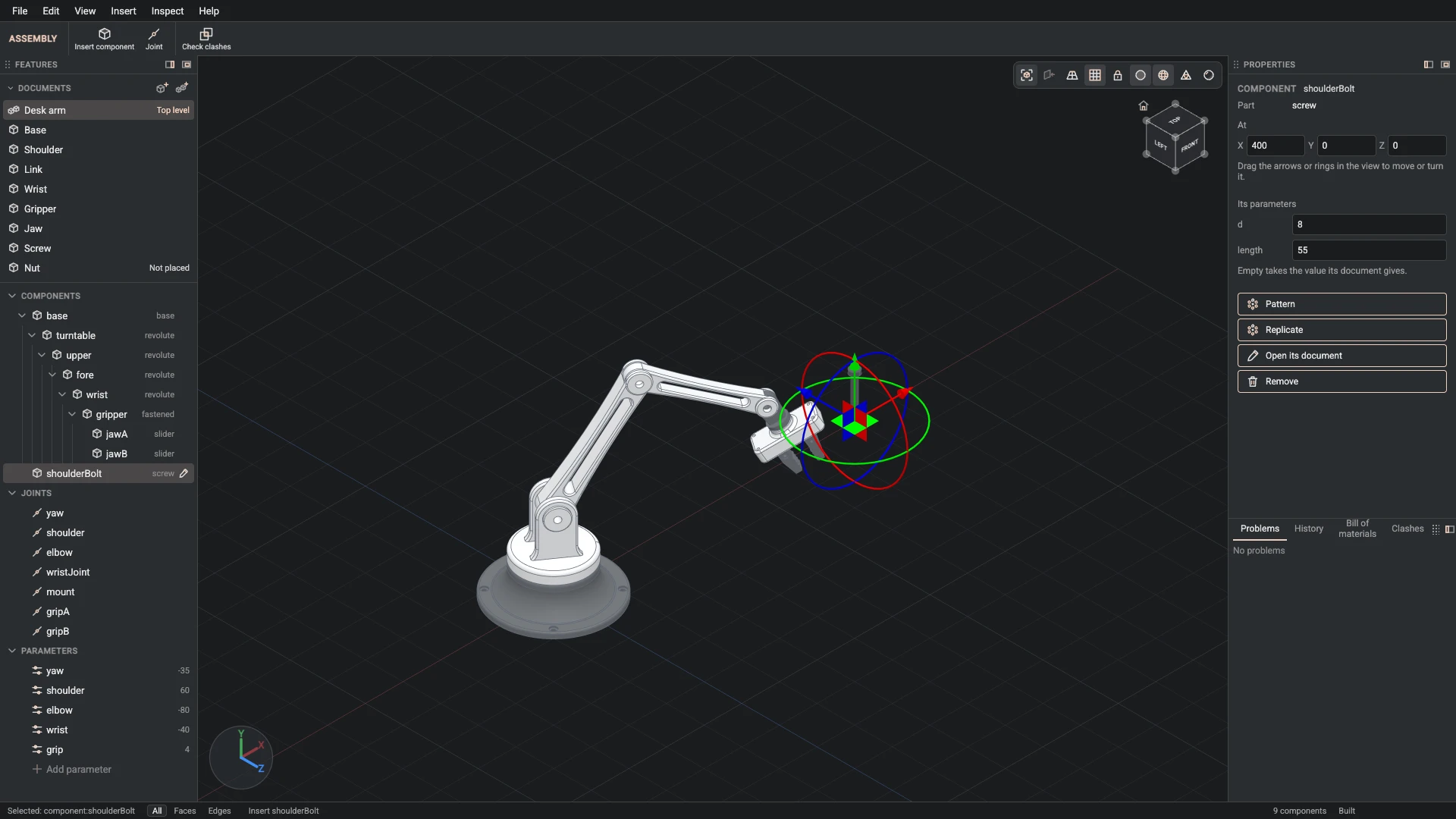
Insert component, from Insert > Insert component: id shoulderBolt, part screw.
Insert the screw document as the shoulder bolt, 8 mm across and 55 mm long.
-
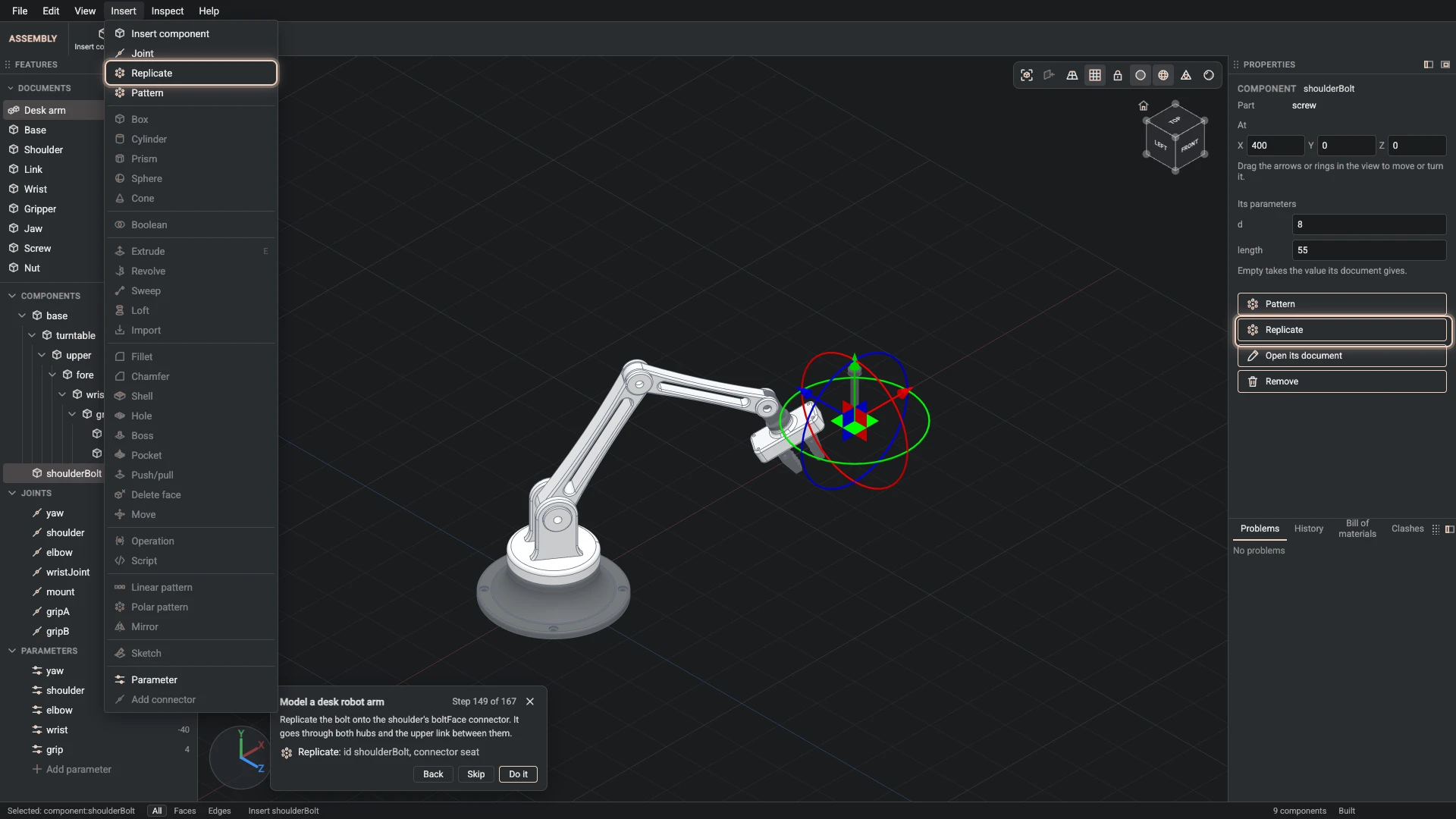
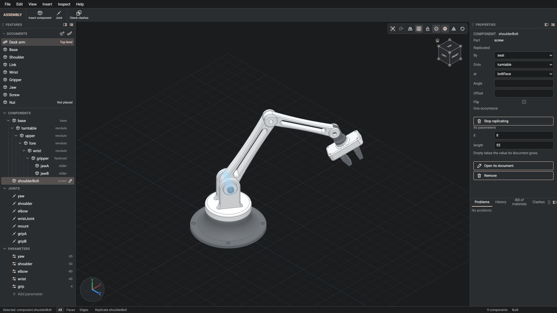
Replicate, from Insert > Replicate: id shoulderBolt, connector seat.
Replicate the bolt onto the shoulder's boltFace connector. It goes through both hubs and the upper link between them.
-
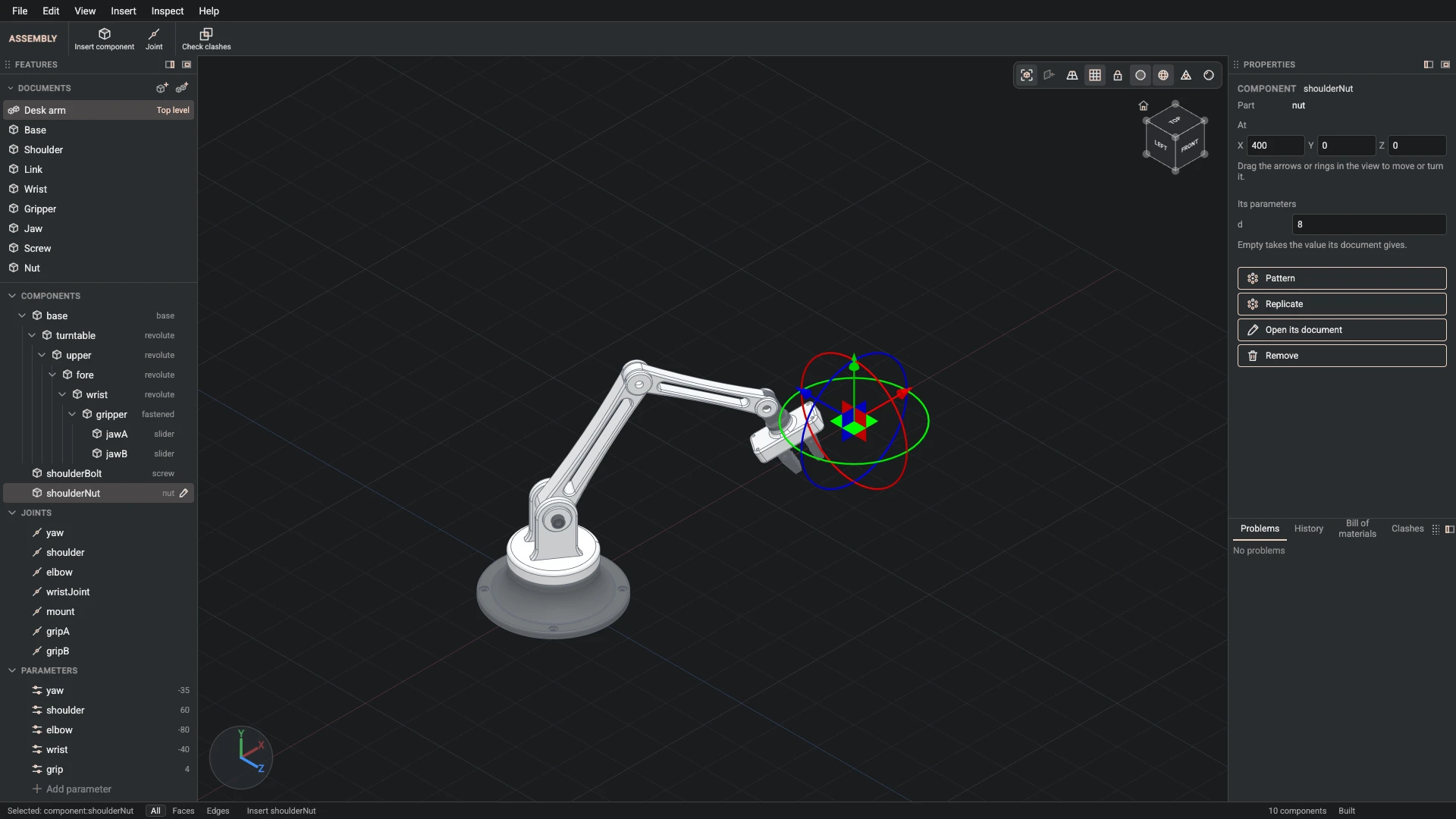
Insert component, from Insert > Insert component: id shoulderNut, part nut.
Insert the nut document for the shoulder bolt.
-
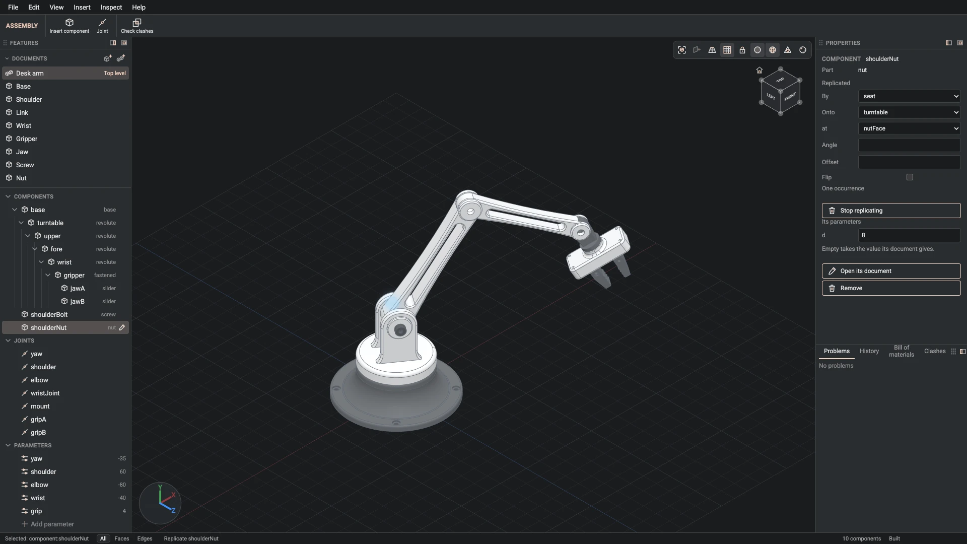
Replicate, from Insert > Replicate: id shoulderNut, connector seat.
Replicate the nut onto the shoulder's nutFace connector, on the other side.
-
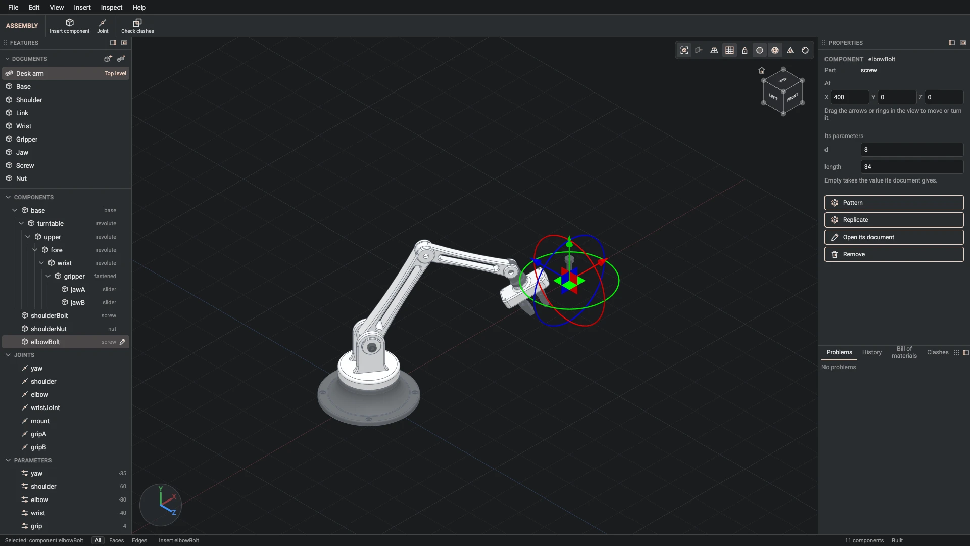
Insert component, from Insert > Insert component: id elbowBolt, part screw.
Insert a screw as the elbow bolt, 8 by 34 mm.
-
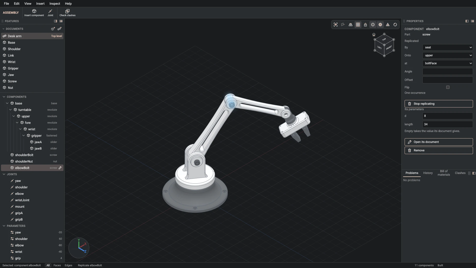
Replicate, from Insert > Replicate: id elbowBolt, connector seat.
Replicate it onto the upper link's boltFace connector.
-
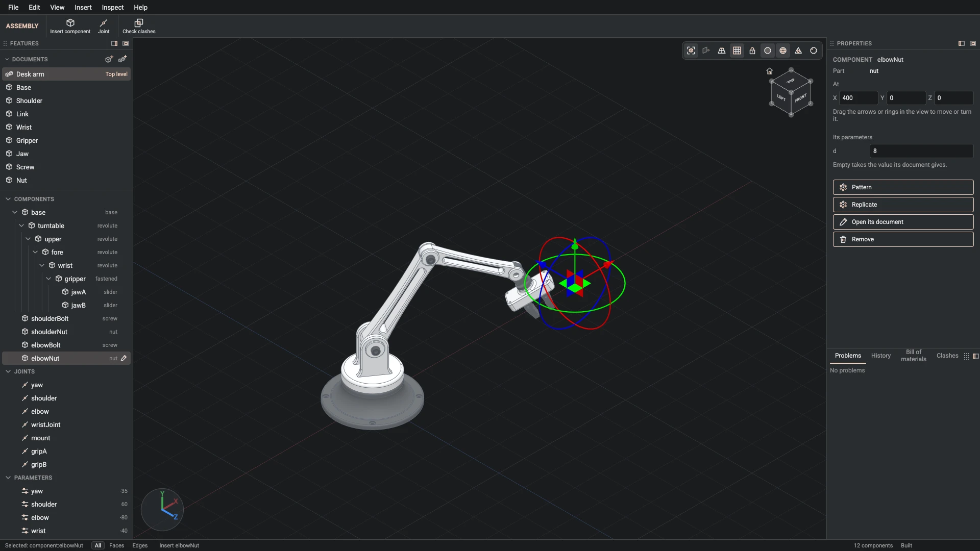
Insert component, from Insert > Insert component: id elbowNut, part nut.
Insert a nut for the elbow.
-
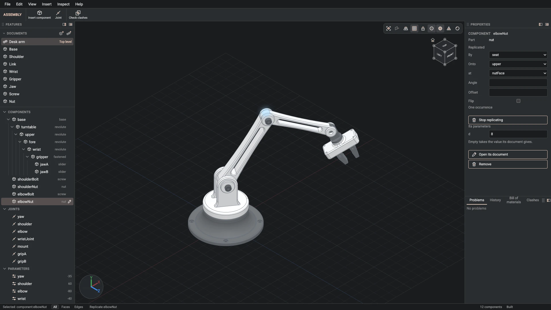
Replicate, from Insert > Replicate: id elbowNut, connector seat.
Replicate it onto the upper link's nutFace connector.
-
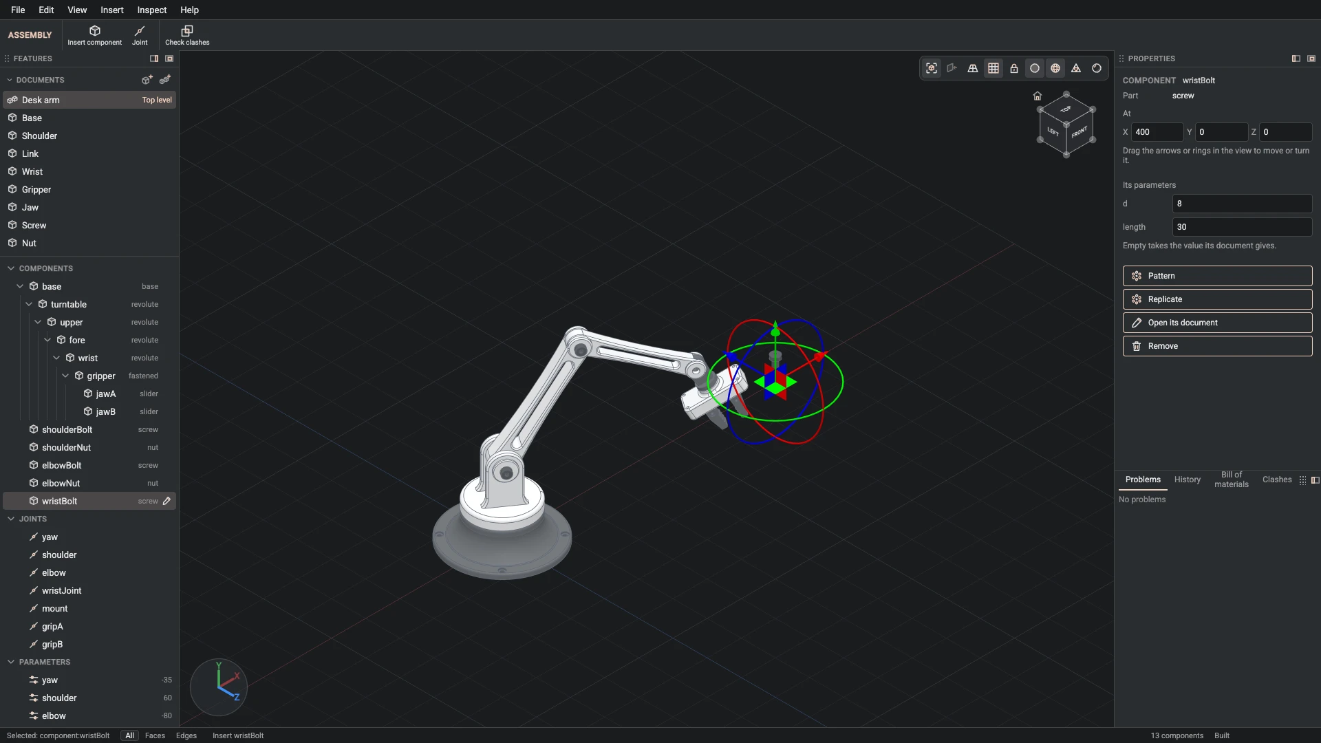
Insert component, from Insert > Insert component: id wristBolt, part screw.
Insert a screw as the wrist bolt, 8 by 30 mm.
-
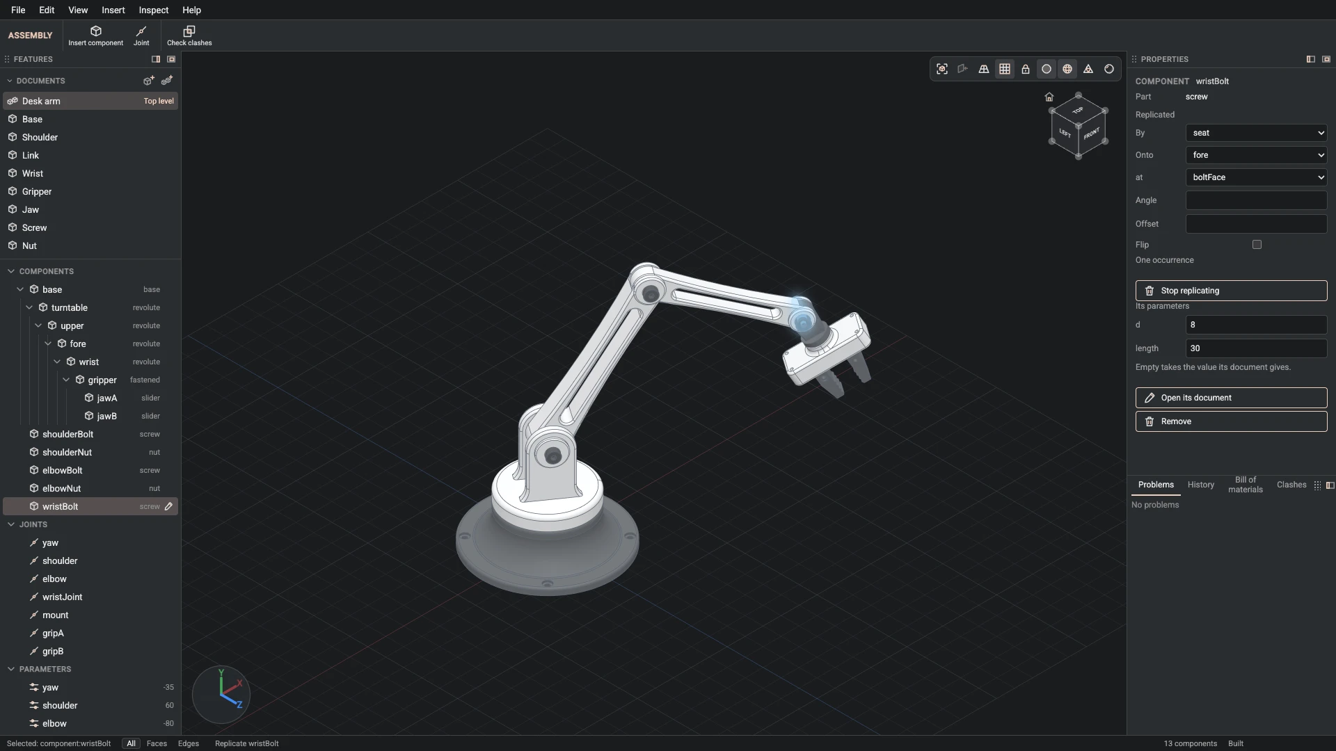
Replicate, from Insert > Replicate: id wristBolt, connector seat.
Replicate it onto the forearm's boltFace connector.
-
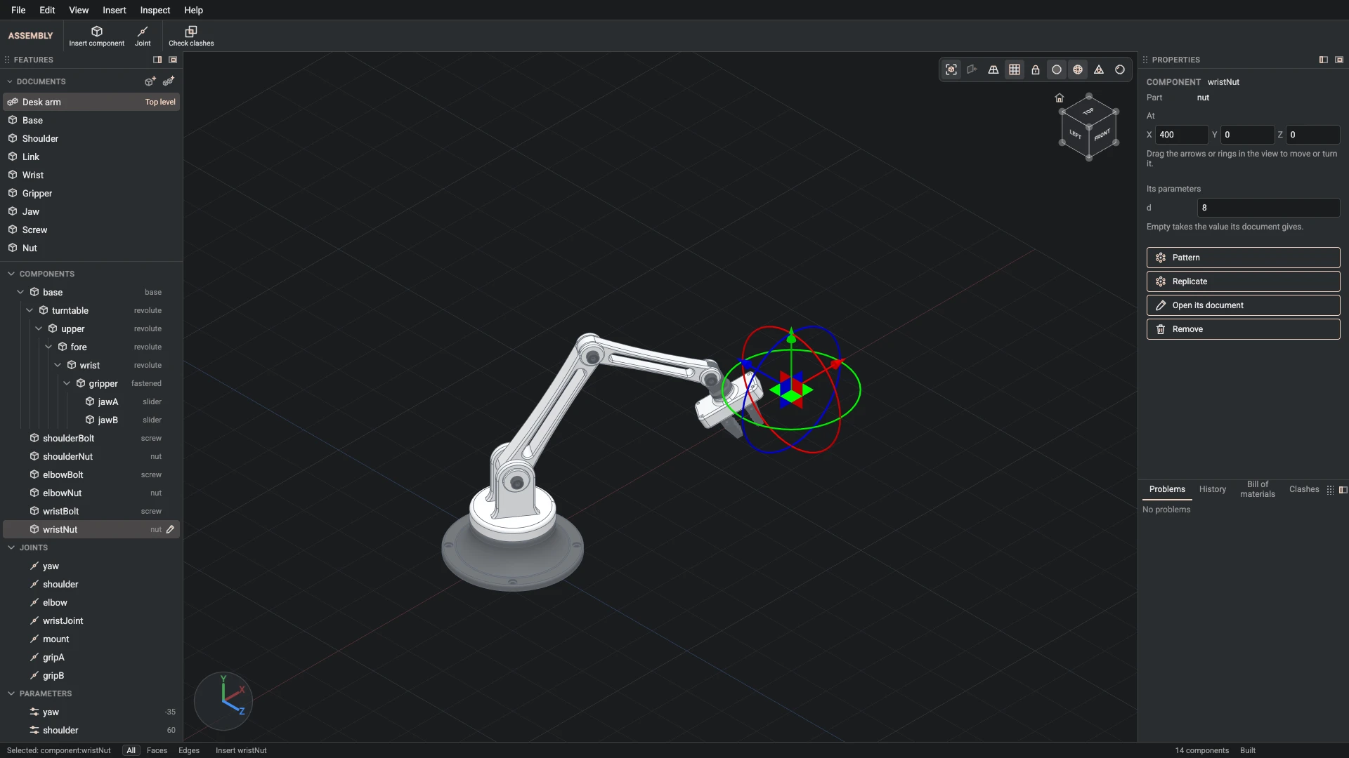
Insert component, from Insert > Insert component: id wristNut, part nut.
Insert a nut for the wrist.
-
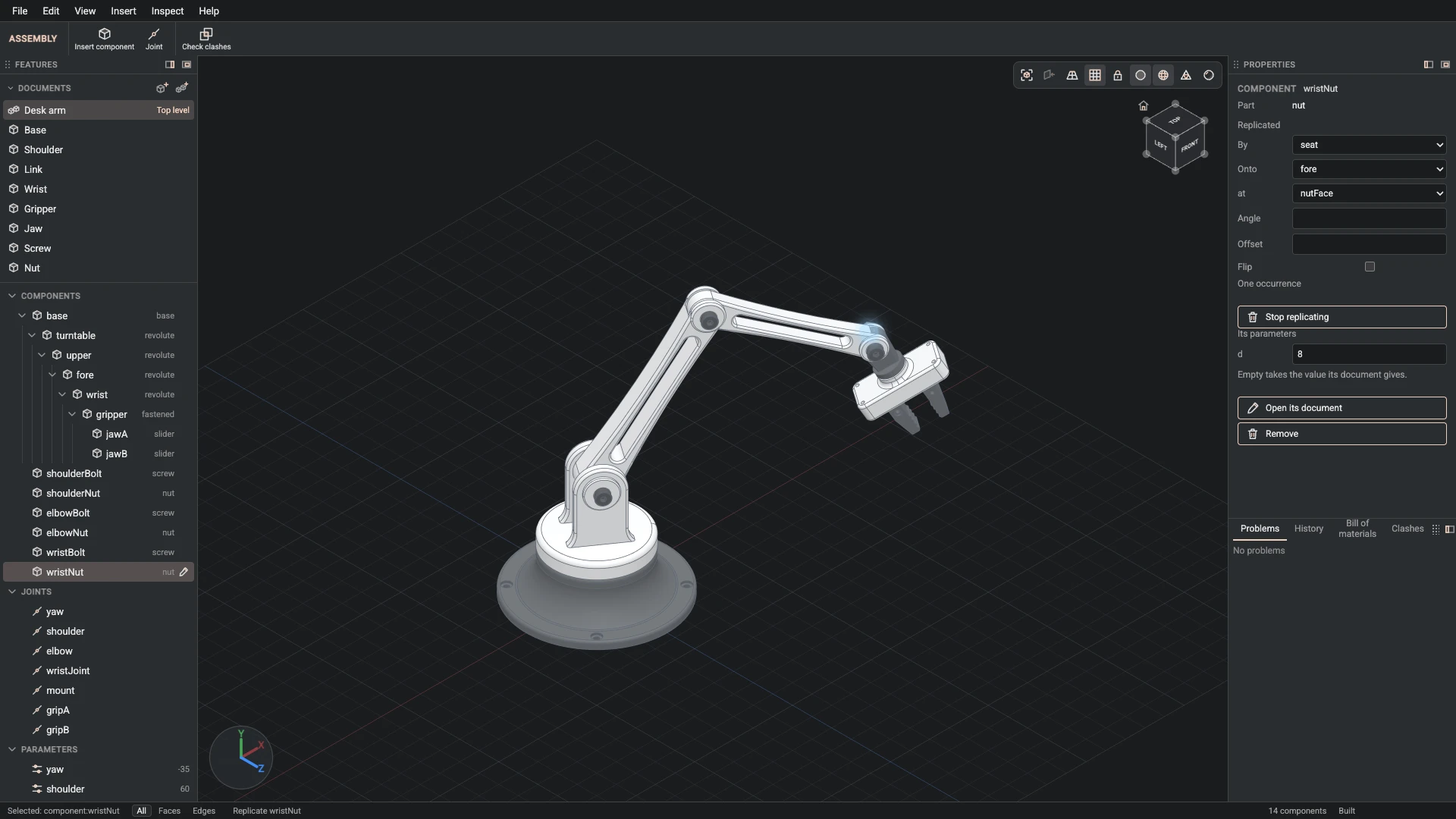
Replicate, from Insert > Replicate: id wristNut, connector seat.
Replicate it onto the forearm's nutFace connector.
-
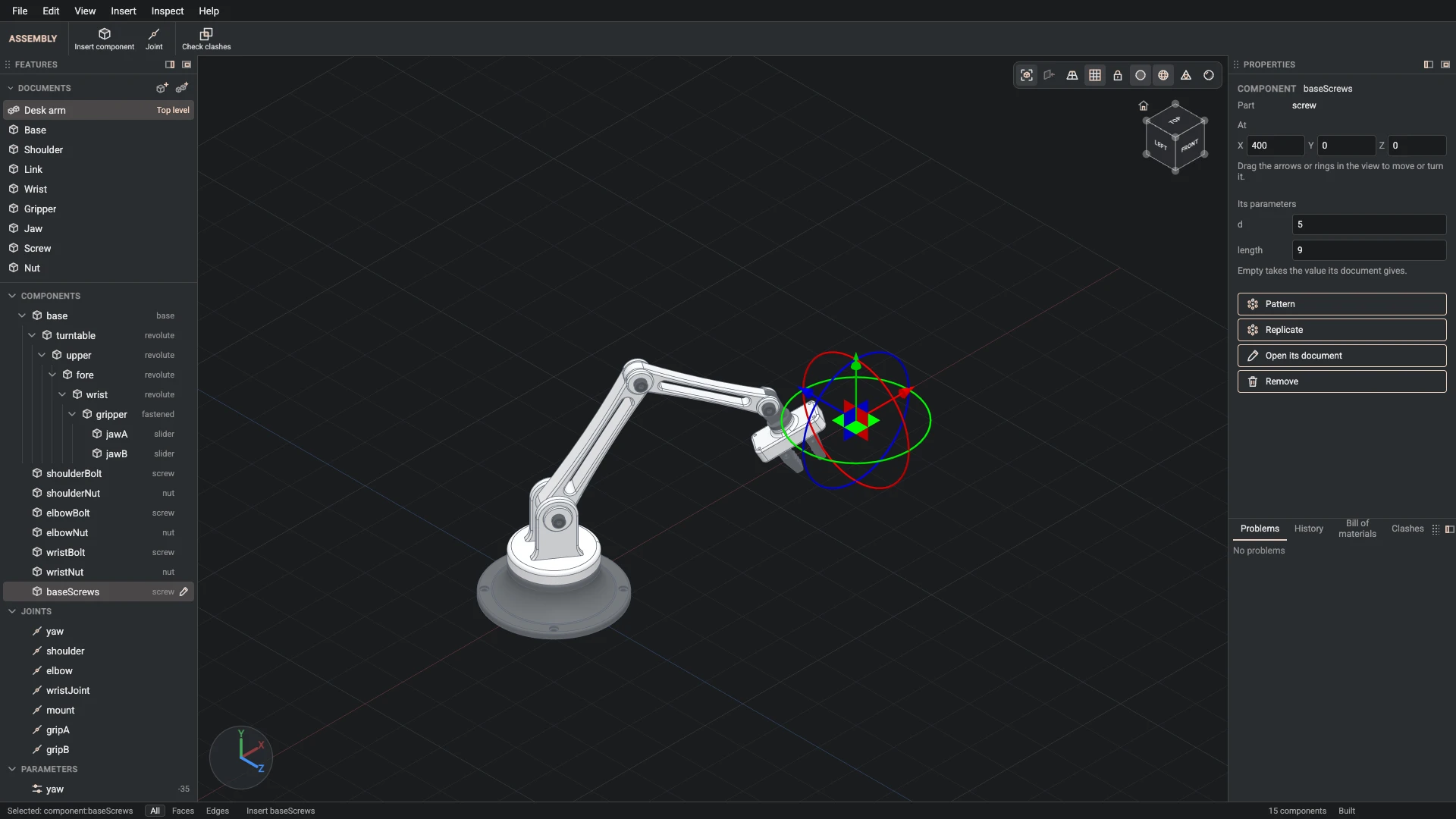
Insert component, from Insert > Insert component: id baseScrews, part screw.
Insert a screw for the base, 5 by 9 mm.
-
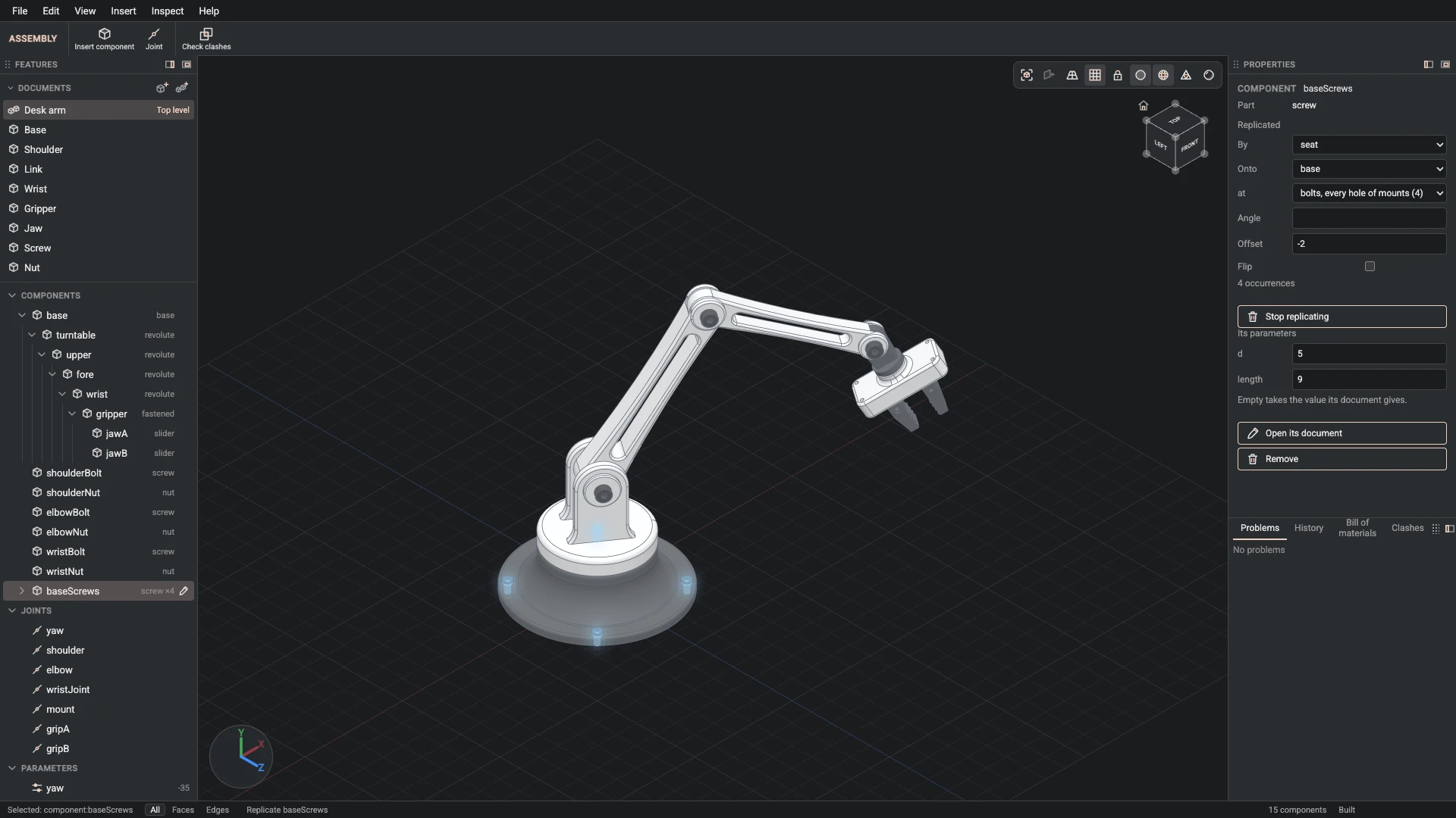
Replicate, from Insert > Replicate: id baseScrews, connector seat, offset -2.
Replicate it onto the base's bolts connector, 2 mm down into the counterbores. One copy lands in each of the four holes.
-
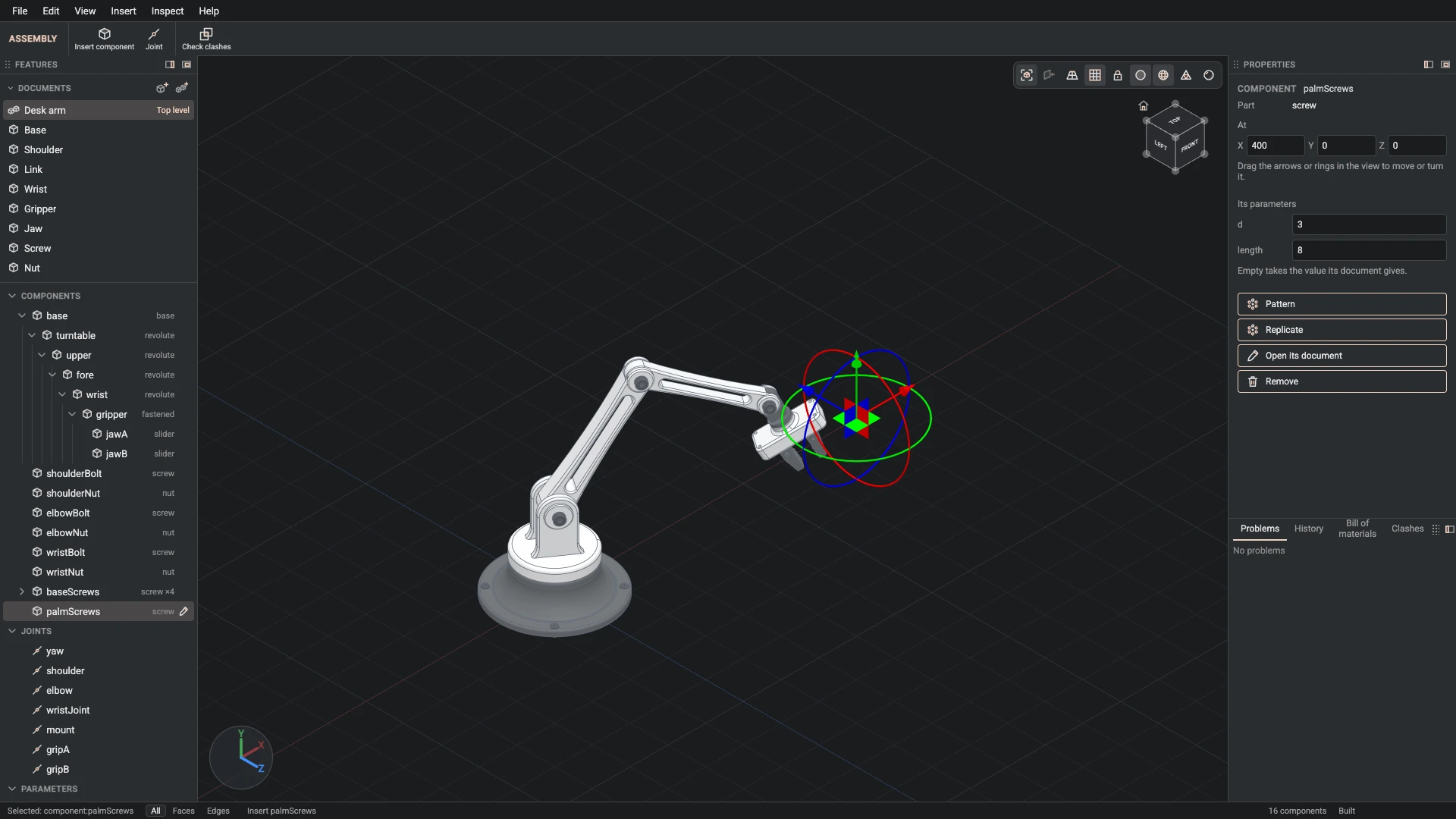
Insert component, from Insert > Insert component: id palmScrews, part screw.
Insert a screw for the gripper's cover, 3 by 8 mm.
-
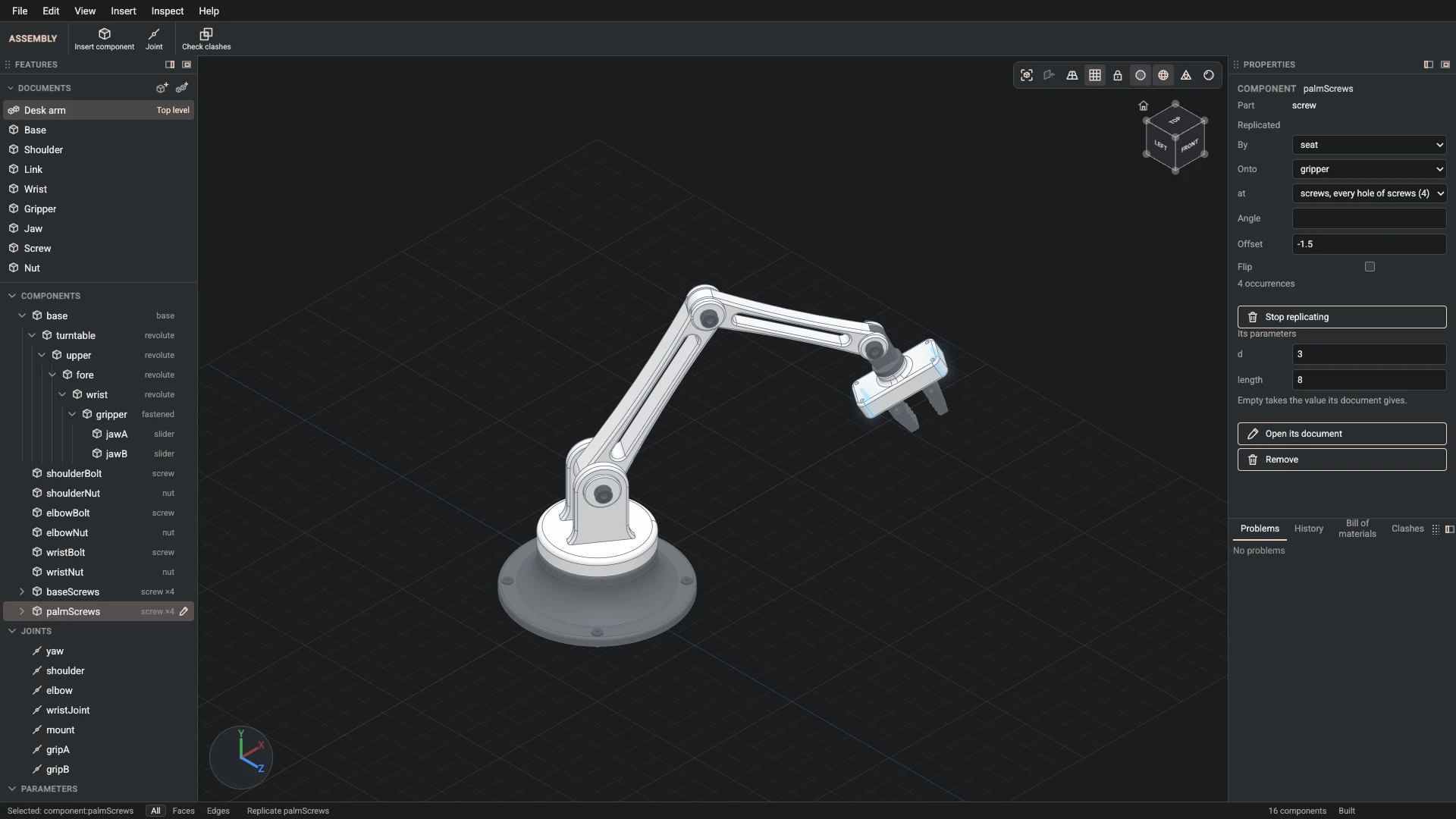
Replicate, from Insert > Replicate: id palmScrews, connector seat, offset -1.5.
Replicate it onto the gripper's screws connector, 1.5 mm down, one in each corner.
-
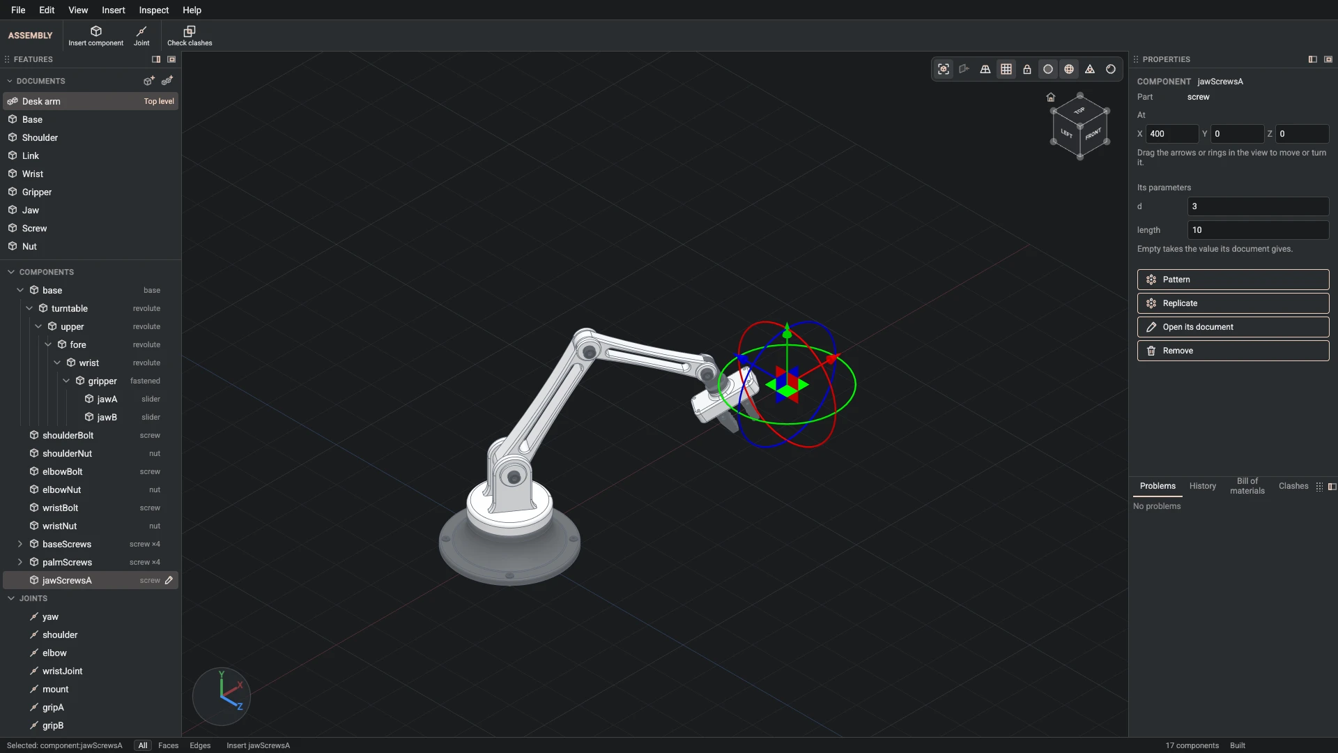
Insert component, from Insert > Insert component: id jawScrewsA, part screw.
Insert a screw for the first jaw, 3 by 10 mm.
-
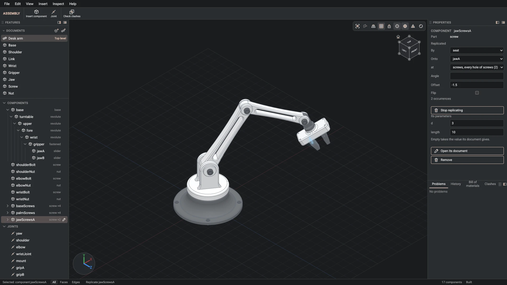
Replicate, from Insert > Replicate: id jawScrewsA, connector seat, offset -1.5.
Replicate it onto the first jaw's screws connector.
-
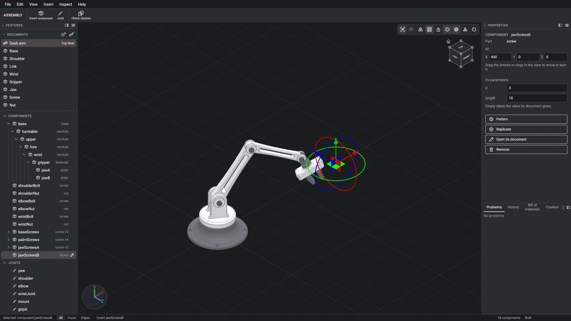
Insert component, from Insert > Insert component: id jawScrewsB, part screw.
Insert a screw for the second jaw.
-
Replicate, from Insert > Replicate: id jawScrewsB, connector seat, offset -1.5.
Replicate it onto the second jaw's screws connector.
Move the arm
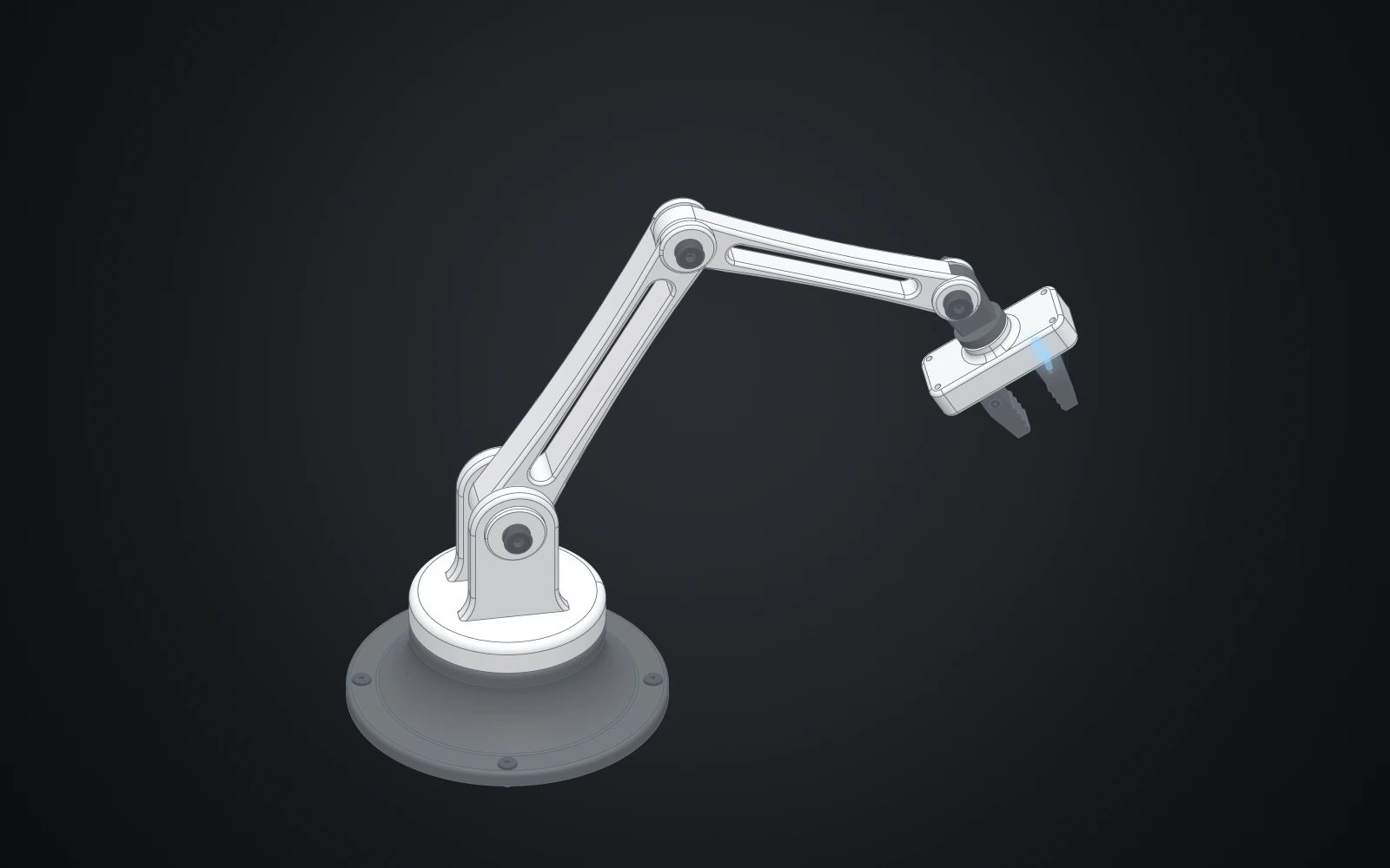
The joints read five parameters of the assembly: yaw, shoulder, elbow and wrist in degrees, and grip in millimetres. Each has a range, so select one in the Features panel and drag its slider in Properties: the arm moves while you drag.
Select a link component to give it other values for its document's parameters, such as a longer length. Both links come from one document, and each keeps its own values.
What you made
- Parts that reuse documents. The screws are one document inserted many times, each at its own diameter and length, and both arm segments are one link document at two sizes.
- Connectors. Every place a part attaches is a connector on a face or a hole. Joints and replicates name connectors, not coordinates, so they follow the parts when sizes change.
- Joints with limits. The turntable, the shoulder, the elbow and the wrist turn about their axes and the jaws slide, each within the range its joint allows, while the gripper is fastened to the wrist.
How the Designer works explains documents, connectors and joints in more depth.
Verified against the product in October 2026