Model a desk robot arm: the base
The base is the part everything else stands on. It is round, so it is drawn as half its section and revolved, the quickest way to model anything that turns about an axis. It also gets the arm's first connectors, the named places an assembly attaches parts to.
Each step shows the Designer as you make it: a feature's dialog filled in with the step's values, with the tutorial card ringing OK, or what the step made. The first time a command appears, a picture shows where it is. The step numbers match the card's in Help > Tutorials.
-
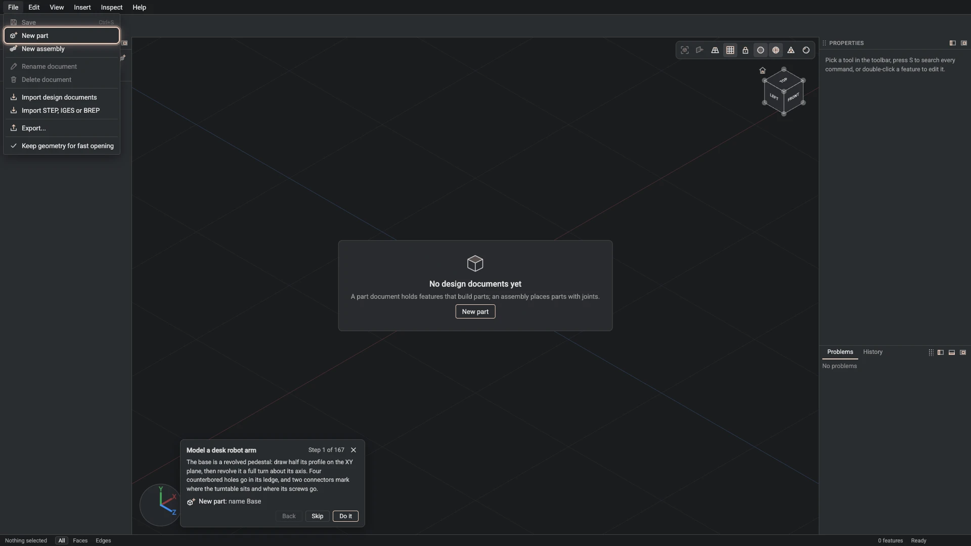
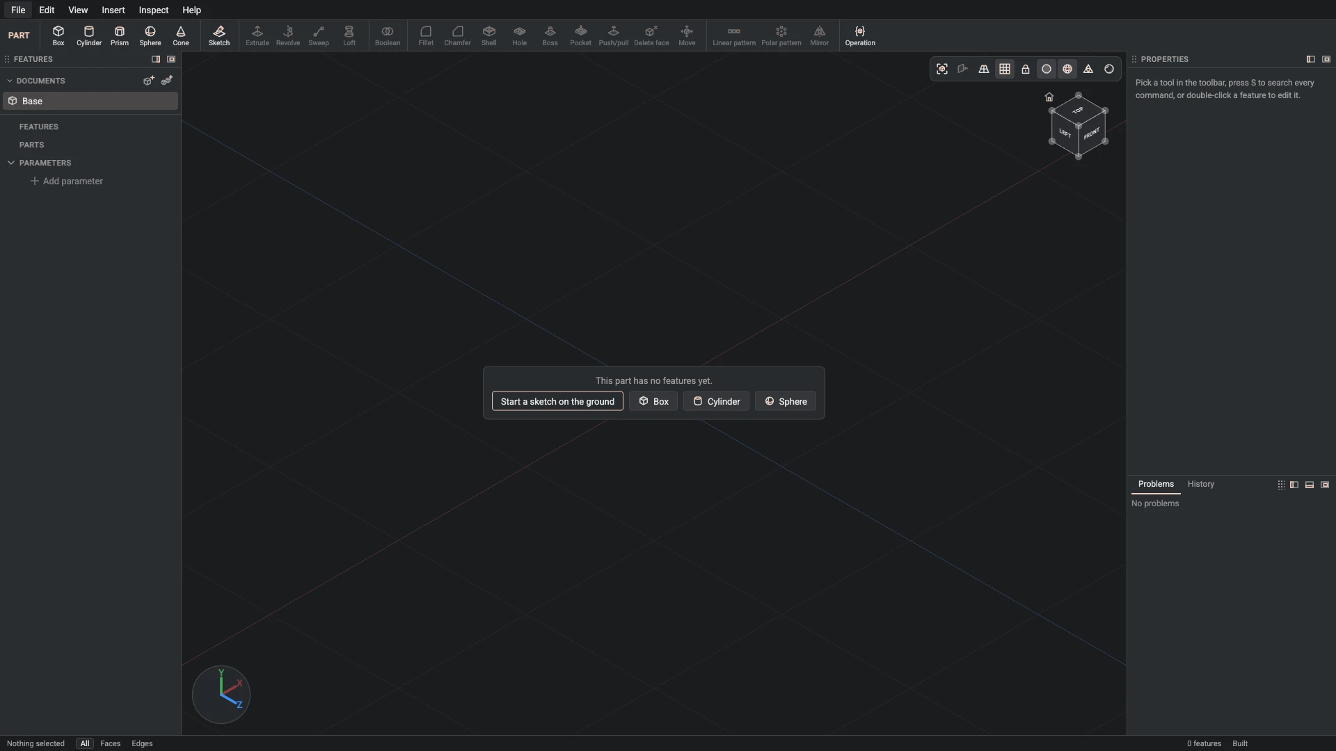
New part, from File > New part: name Base.
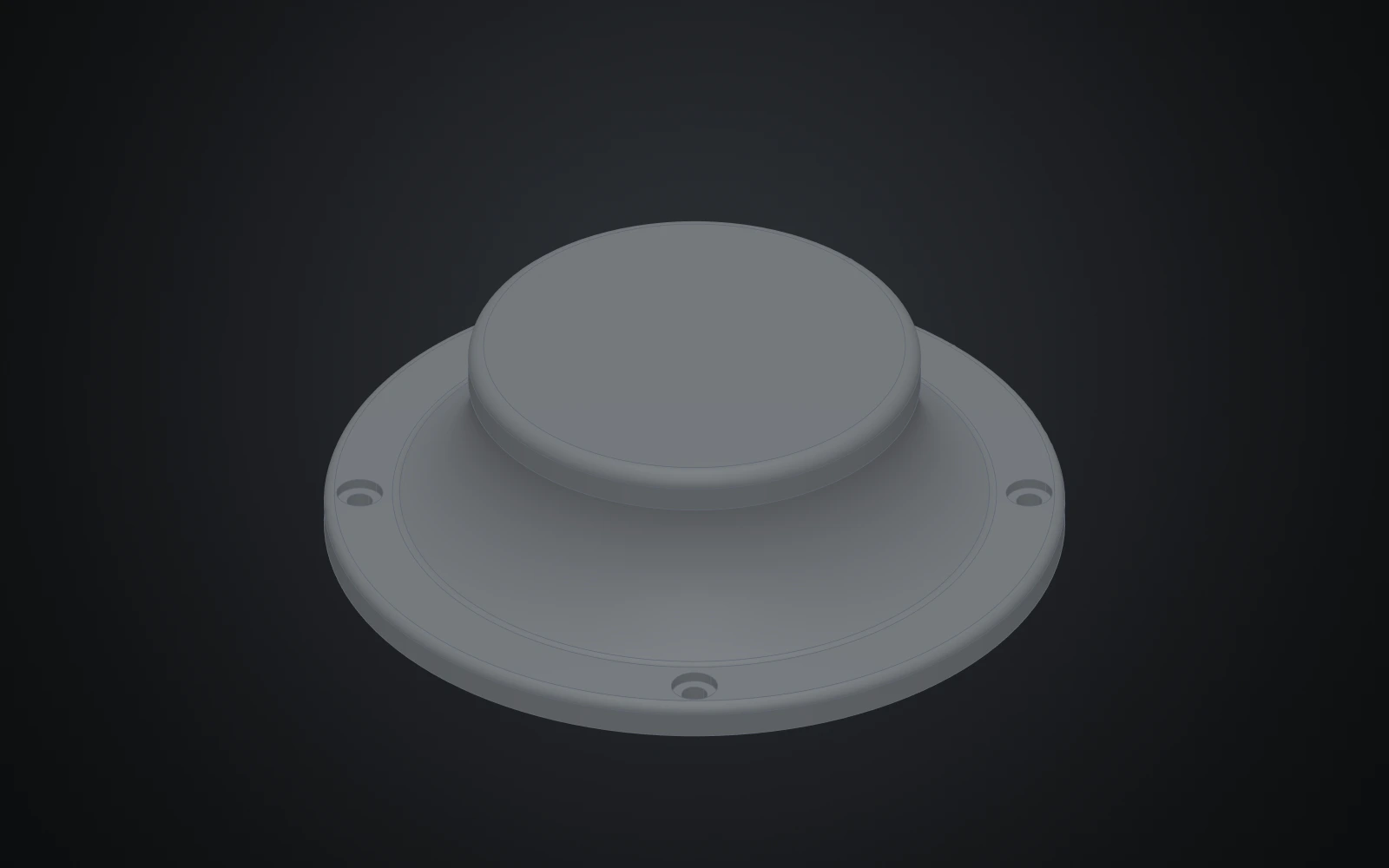
The base is a revolved pedestal: draw half its profile on the XY plane, then revolve it a full turn about its axis. Four counterbored holes go in its ledge, and two connectors mark where the turntable sits and where its screws go.
-
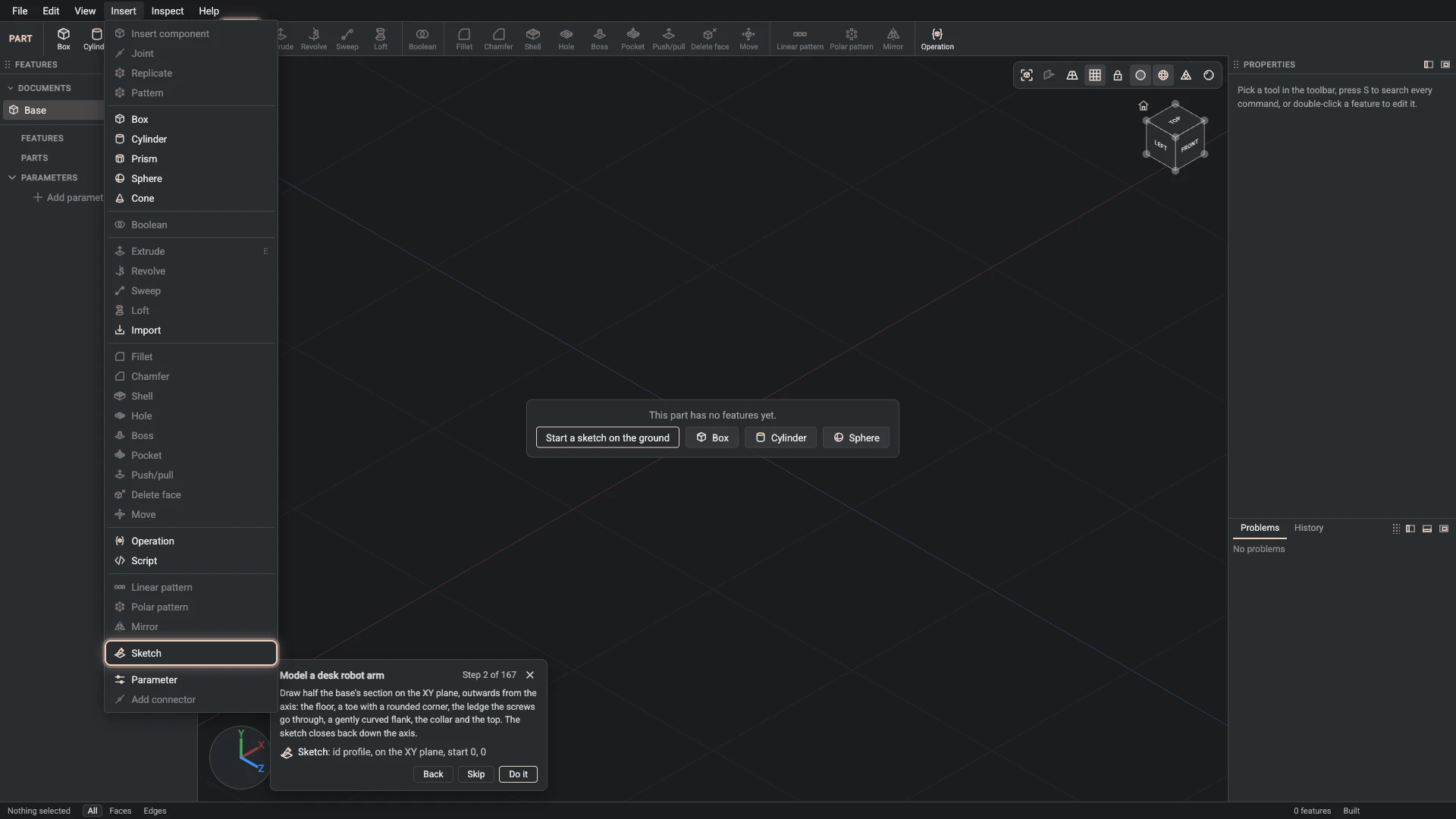
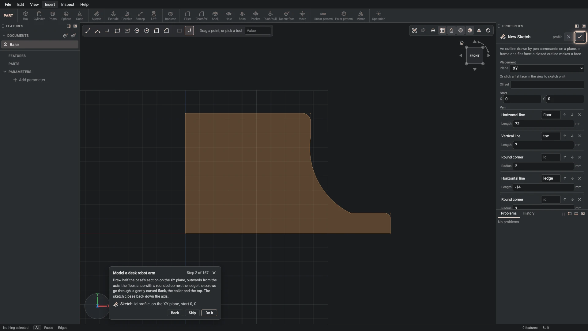
Sketch, from Insert > Sketch: id profile, on the XY plane, start 0, 0.
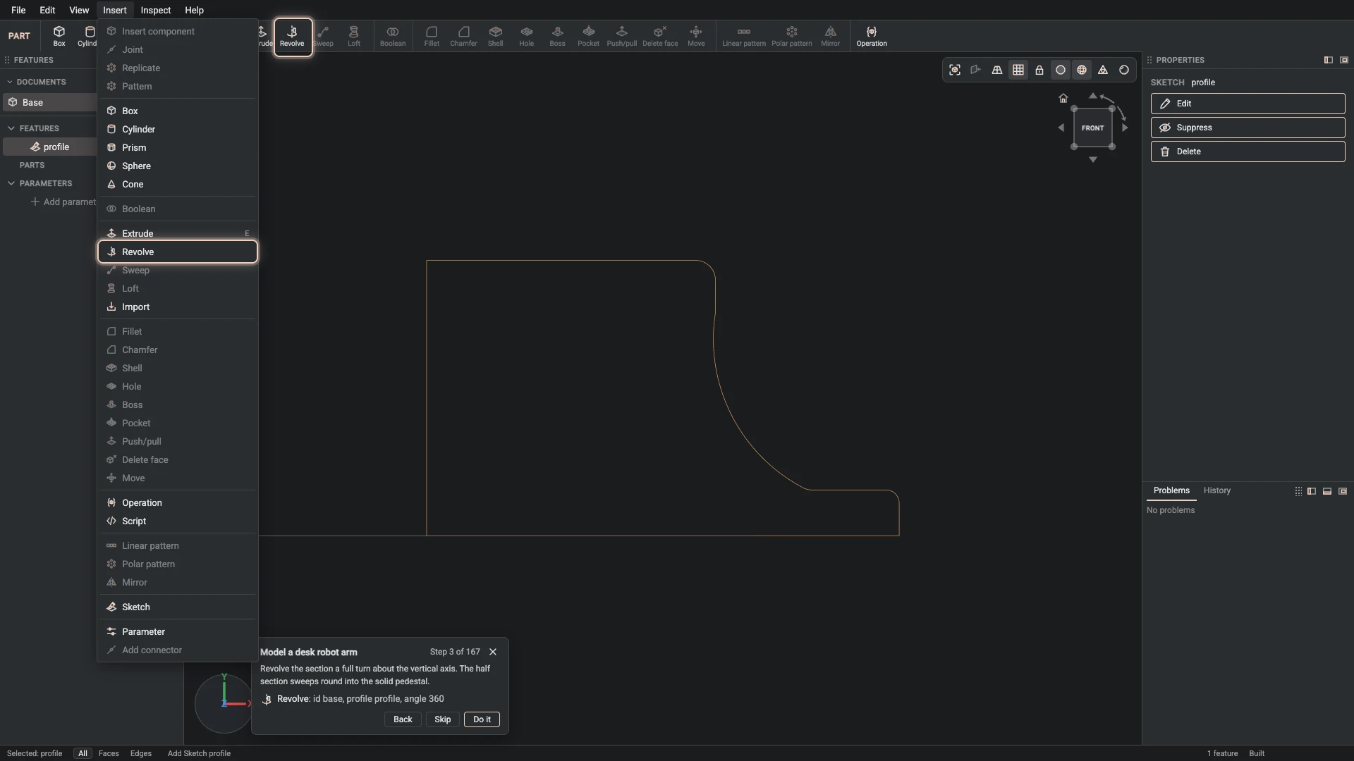
Draw half the base's section on the XY plane, outwards from the axis: the floor, a toe with a rounded corner, the ledge the screws go through, a gently curved flank, the collar and the top. The sketch closes back down the axis.
-
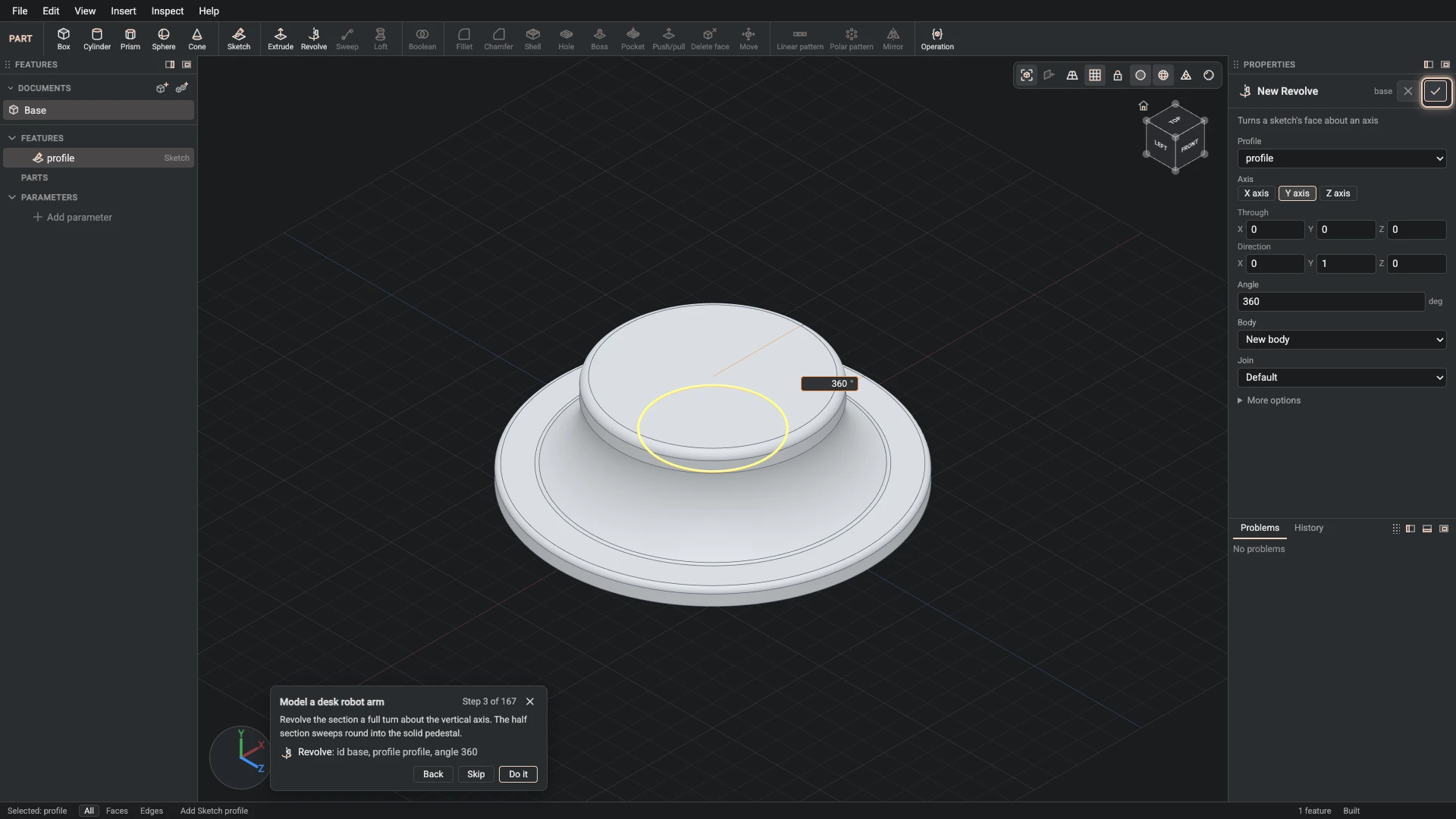
Revolve, from Insert > Revolve: id base, profile profile, angle 360.
Revolve the section a full turn about the vertical axis. The half section sweeps round into the solid pedestal.
-
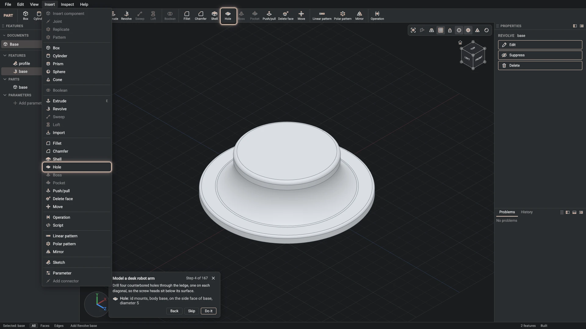
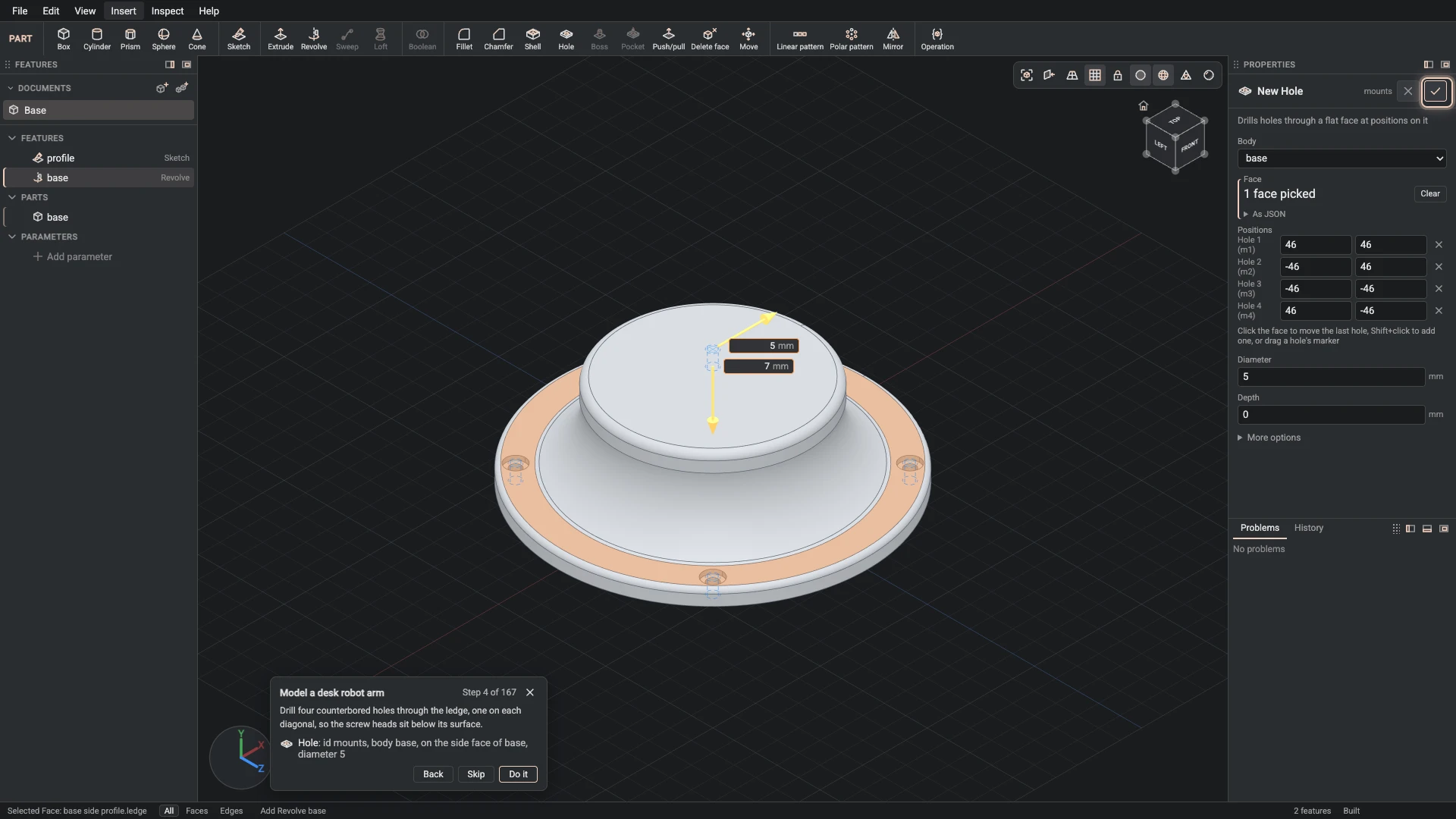
Hole, from Insert > Hole: id mounts, body base, on the side face of base, diameter 5.
Drill four counterbored holes through the ledge, one on each diagonal, so the screw heads sit below its surface.
-
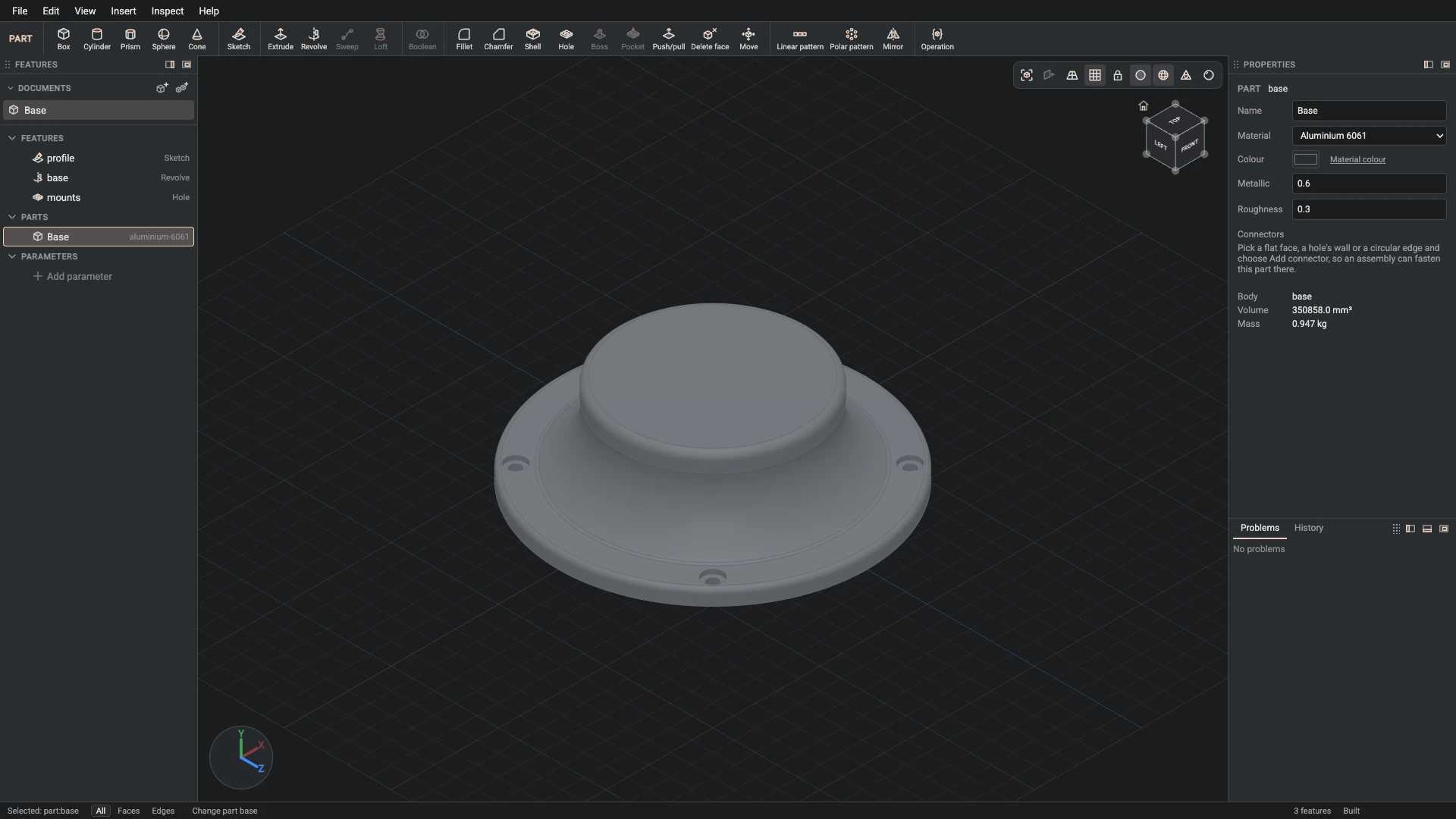
Part properties, from the Properties panel: id base, name Base, material aluminium-6061, color #2a2d31, metallic 0.6, roughness 0.3.
Name the part Base and give it its material and look: dark anodised aluminium.
-
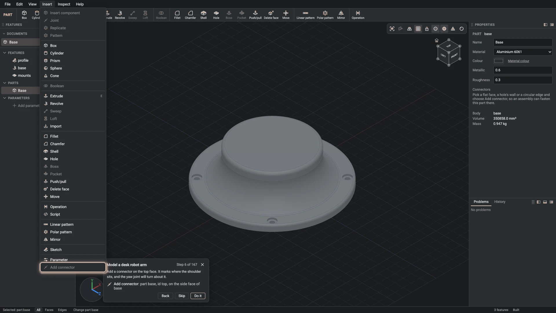
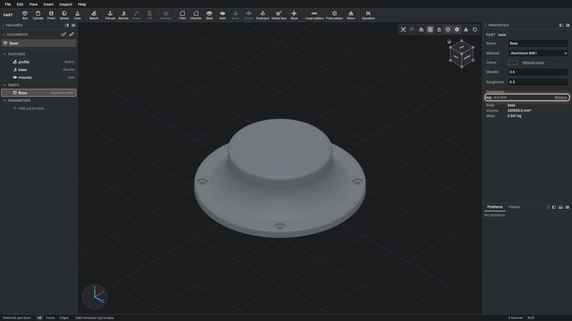
Add connector, from Insert > Add connector: part base, id top, on the side face of base.
Add a connector on the top face. It marks where the shoulder sits, and the yaw joint will turn about it.
-
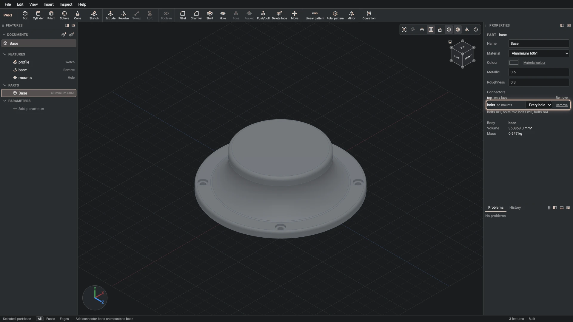
Add connector, from Insert > Add connector: part base, id bolts, on the side face of base, axis the wall face of mounts.
Add a connector on the ledge, its axis along the holes' walls. A screw replicated onto it lands in every hole.
Verified against the product in October 2026