Model a desk robot arm: the link
Both arm segments are this one document. Every size of the link reads one of its five parameters, so the assembly can insert it twice and give each copy its own values. The steps start with the parameters, then draw every feature in terms of them.
Each step shows the Designer as you make it: a feature's dialog filled in with the step's values, with the tutorial card ringing OK, or what the step made. The first time a command appears, a picture shows where it is. The step numbers match the card's in Help > Tutorials.
-
New part, from File > New part: name Link.
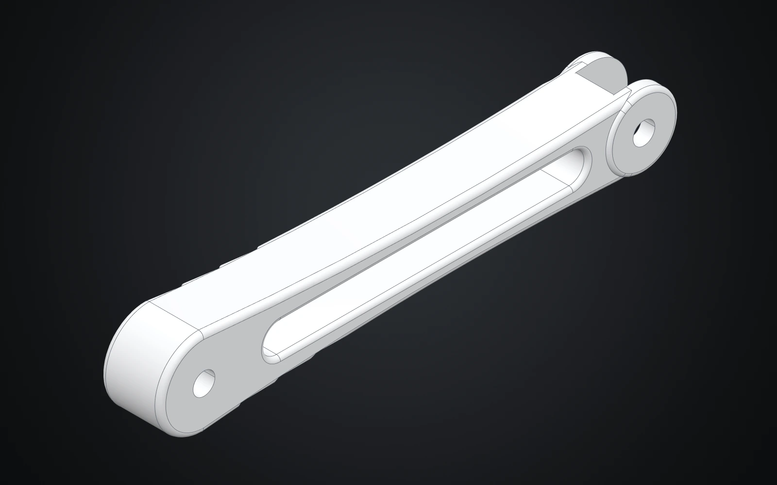
One link document serves both arm segments. Five parameters (length, width, gap, hub and tip) drive a waisted side profile, a forked hub at the far end, a lightening window and the two pivot holes.
-
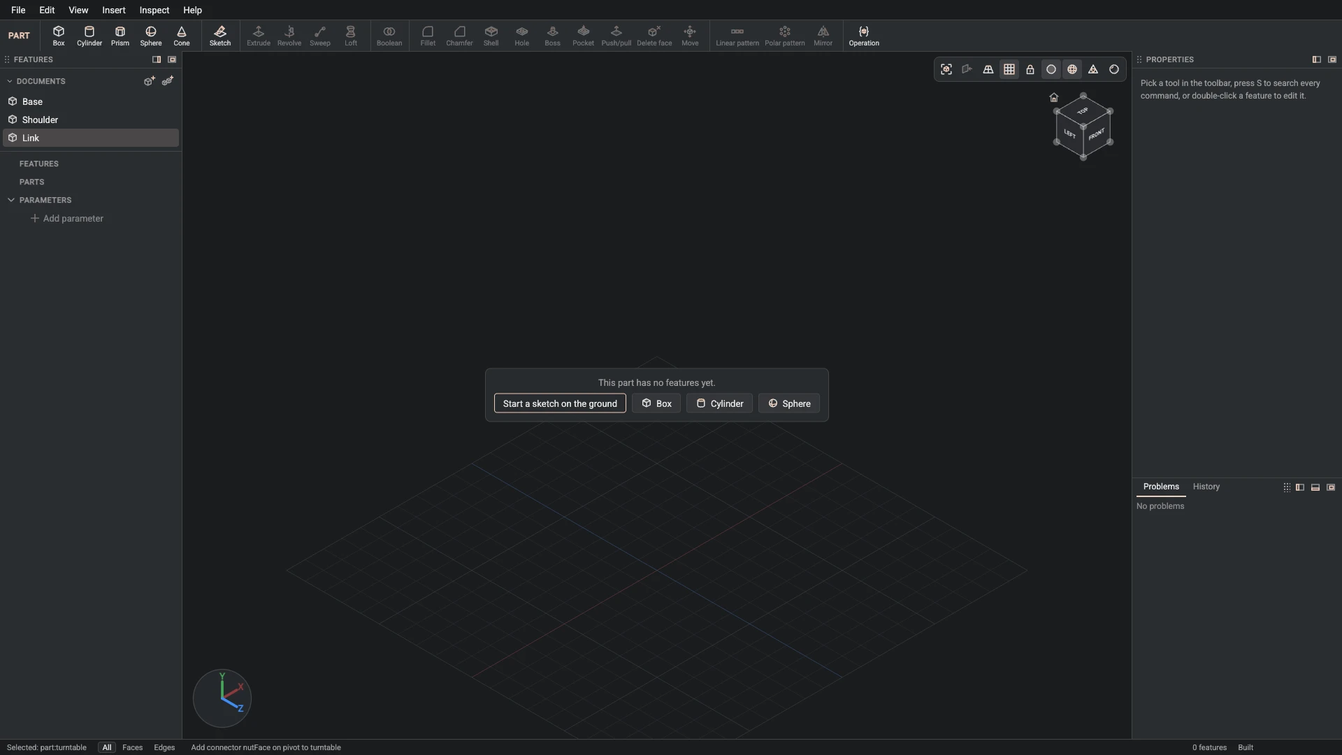
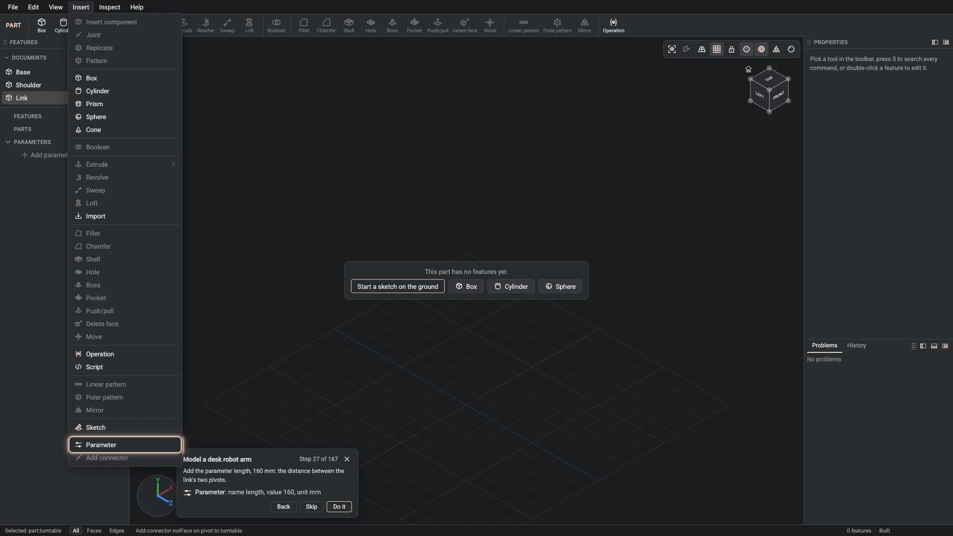
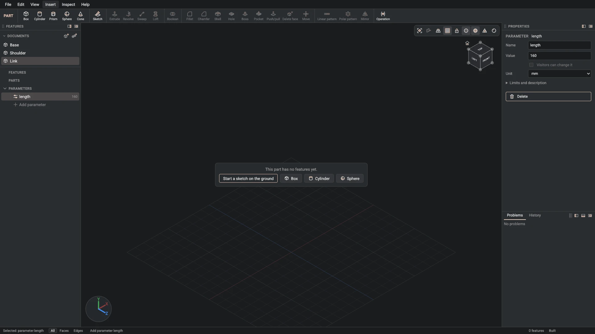
Parameter, from Insert > Parameter: name length, value 160, unit mm.
Add the parameter length, 160 mm: the distance between the link's two pivots.
-
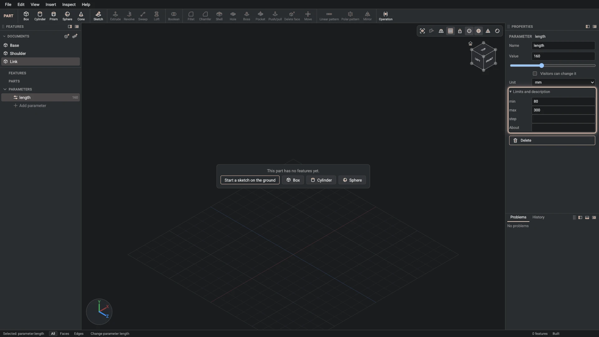
Change parameter, from the Properties panel: name length, min 80, max 300.
Give length its range, 80 to 300 mm: the values the design is drawn for.
-
Parameter, from Insert > Parameter: name width, value 22, unit mm.
Add the parameter width, 22 mm: how thick the link is.
-
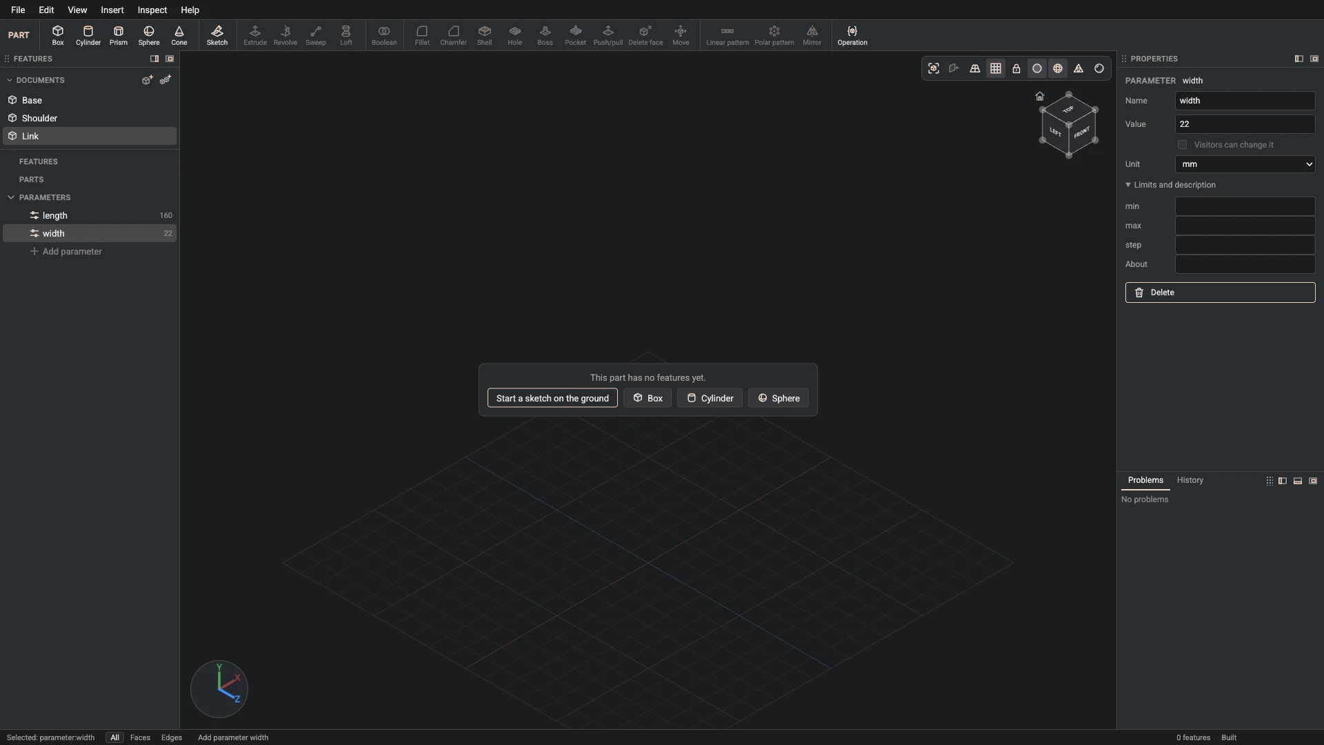
Change parameter, from the Properties panel: name width, min 10, max 40.
Give width its range, 10 to 40 mm: the values the design is drawn for.
-
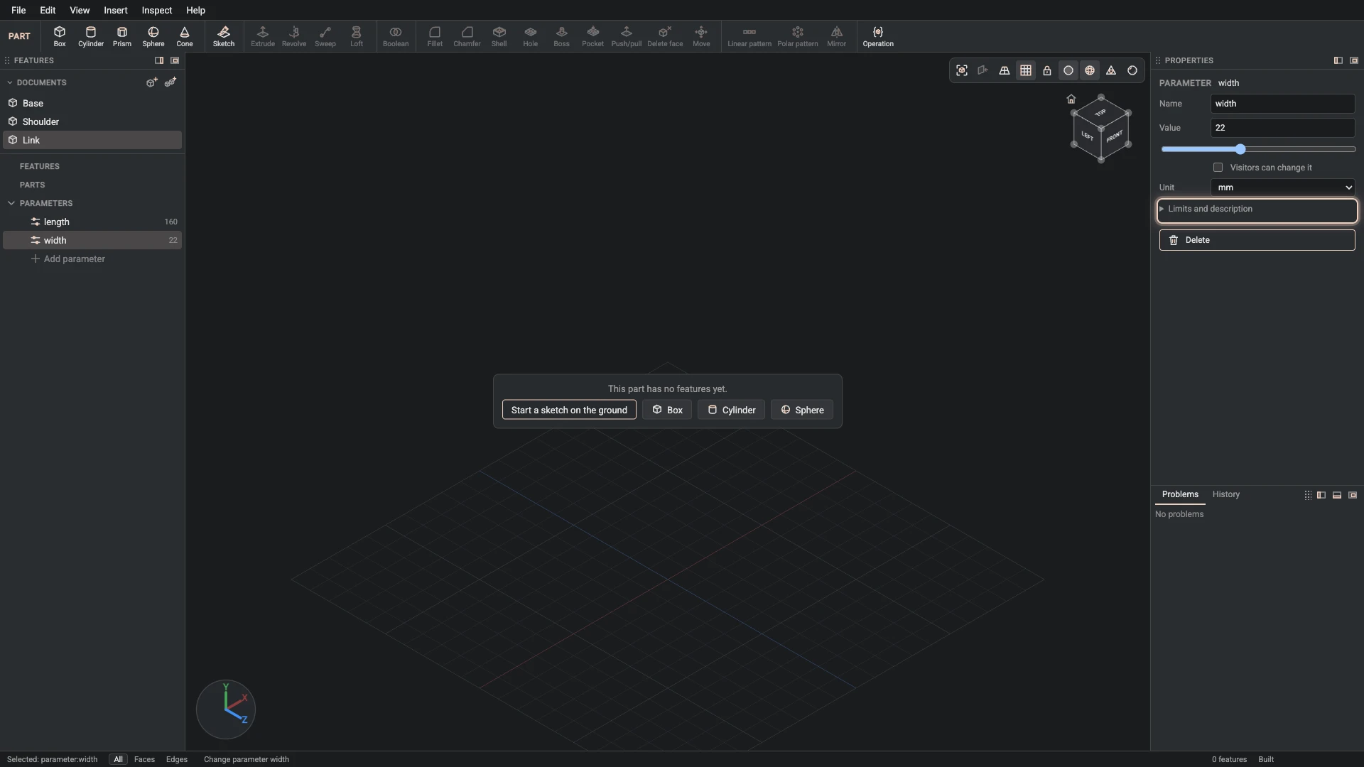
Parameter, from Insert > Parameter: name gap, value 14, unit mm.
Add the parameter gap, 14 mm: the width of the fork at the far end, which the next part fits into.
-
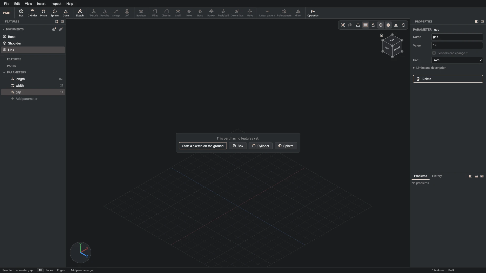
Change parameter, from the Properties panel: name gap, min 6, max 30.
Give gap its range, 6 to 30 mm: the values the design is drawn for.
-
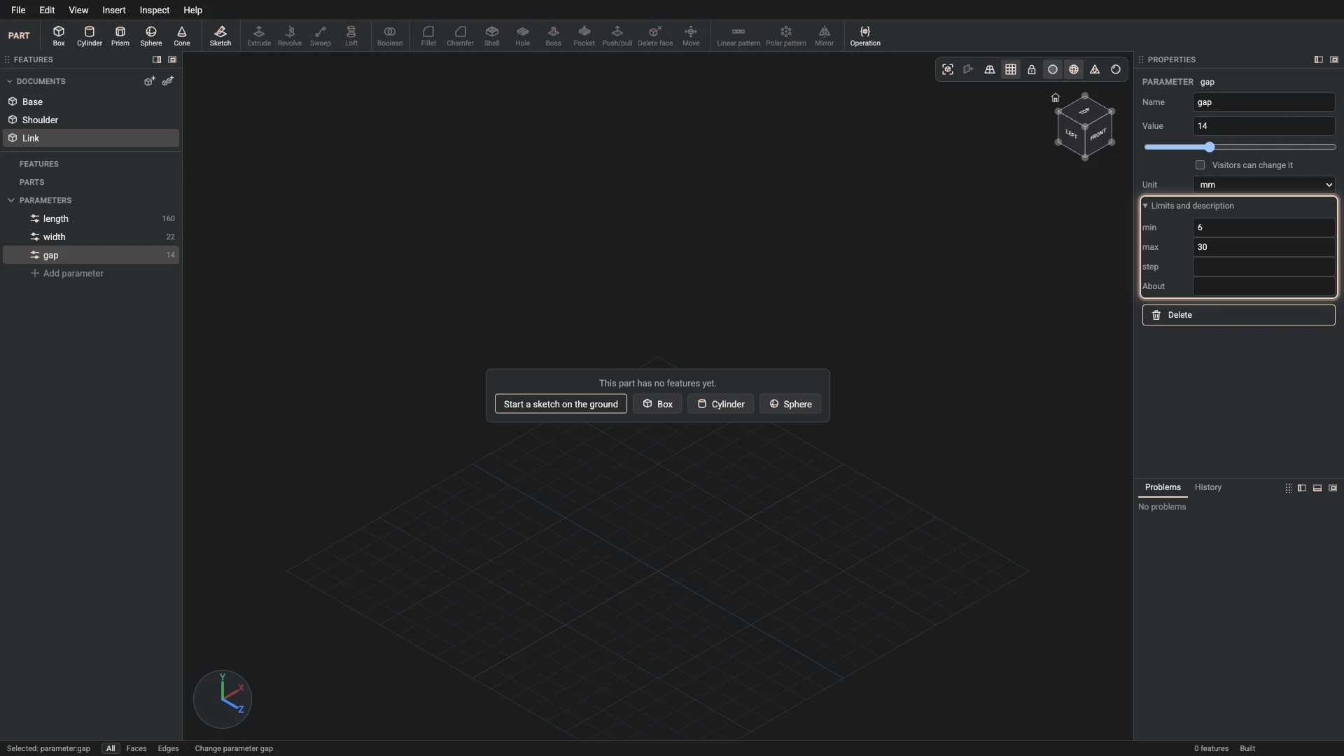
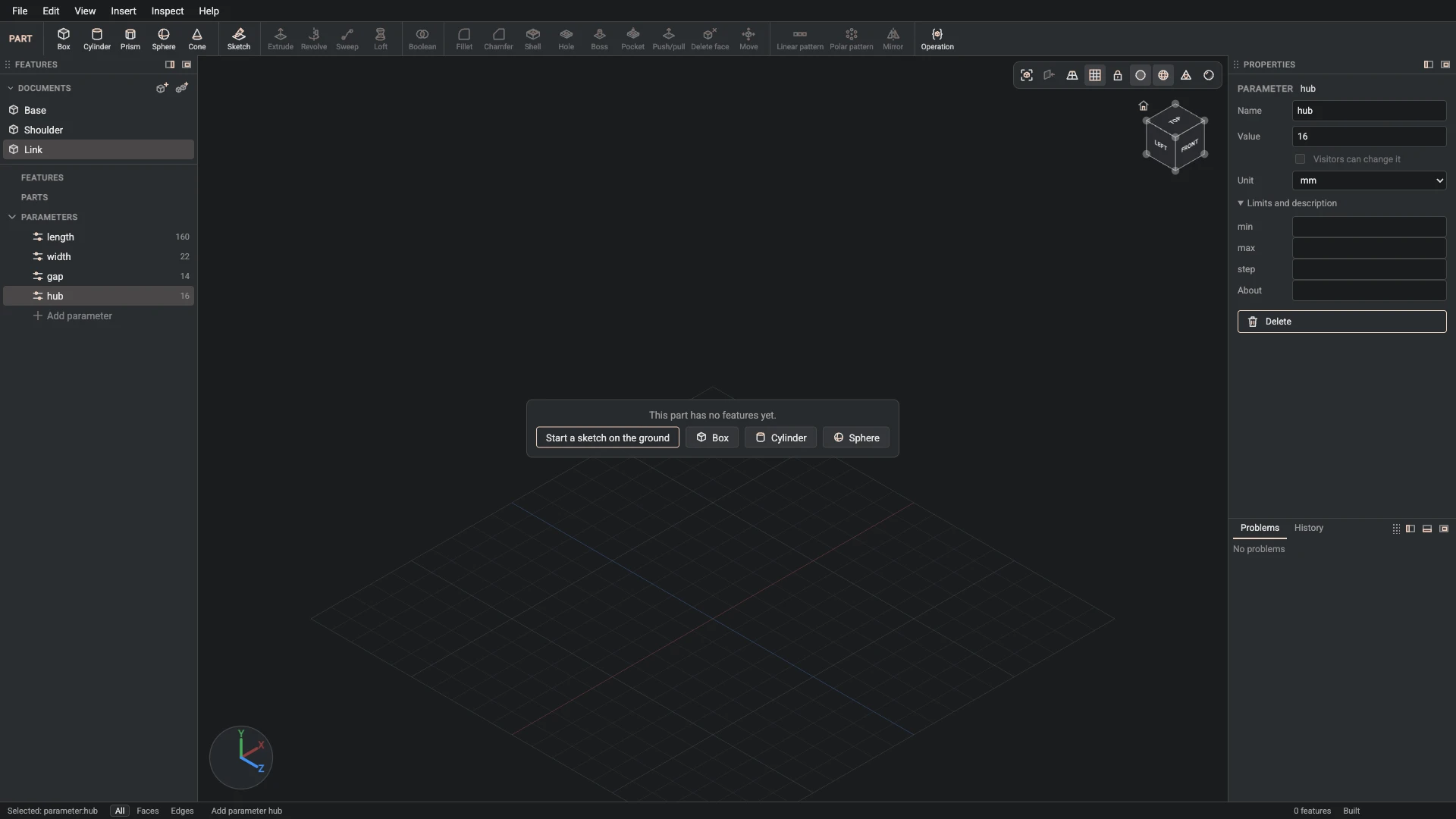
Parameter, from Insert > Parameter: name hub, value 16, unit mm.
Add the parameter hub, 16 mm: the radius of the rounded heel at the near pivot.
-
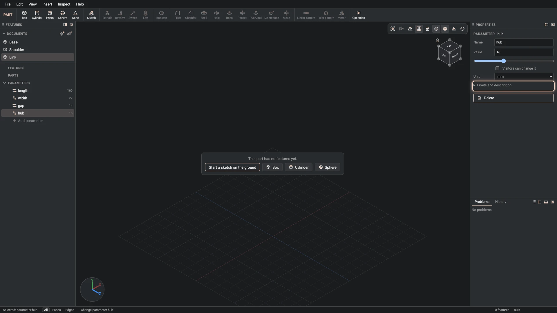
Change parameter, from the Properties panel: name hub, min 8, max 30.
Give hub its range, 8 to 30 mm: the values the design is drawn for.
-
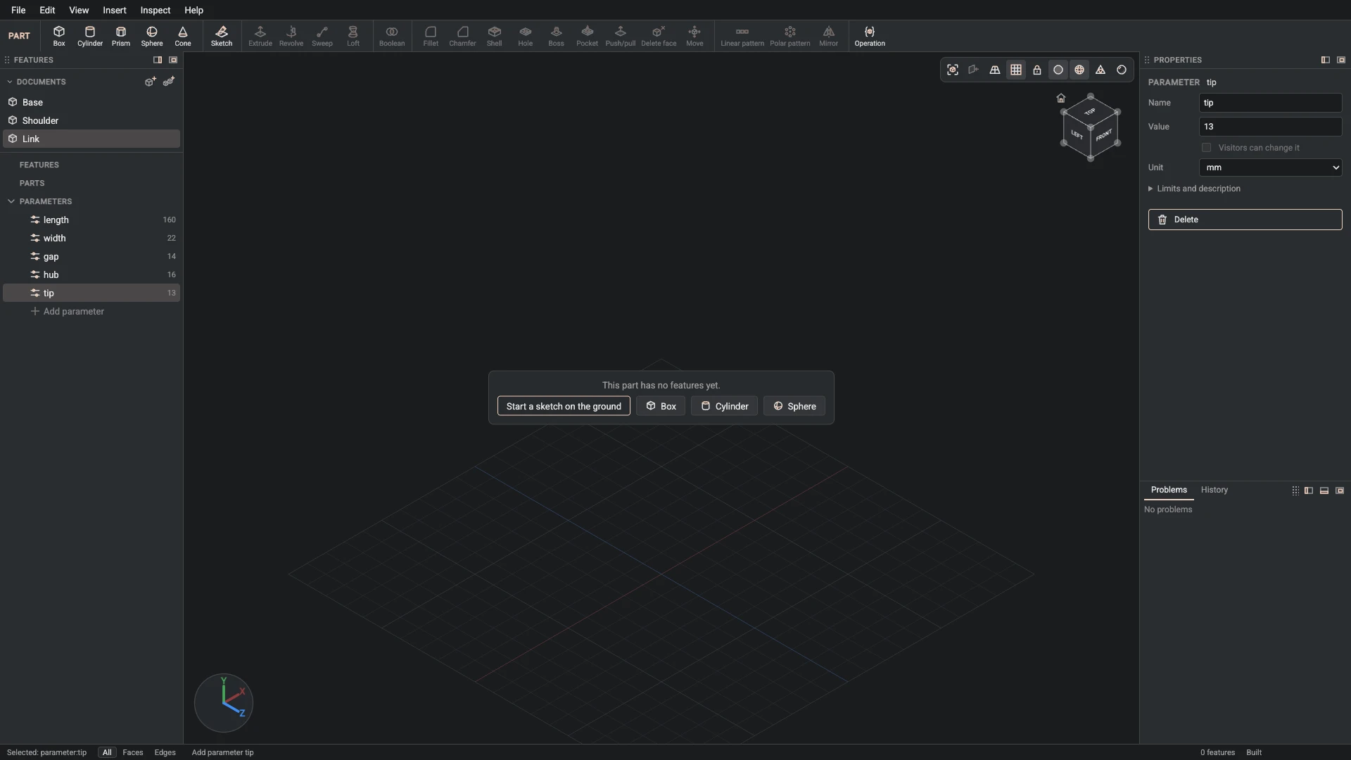
Parameter, from Insert > Parameter: name tip, value 13, unit mm.
Add the parameter tip, 13 mm: the radius of the rounded nose at the far pivot.
-
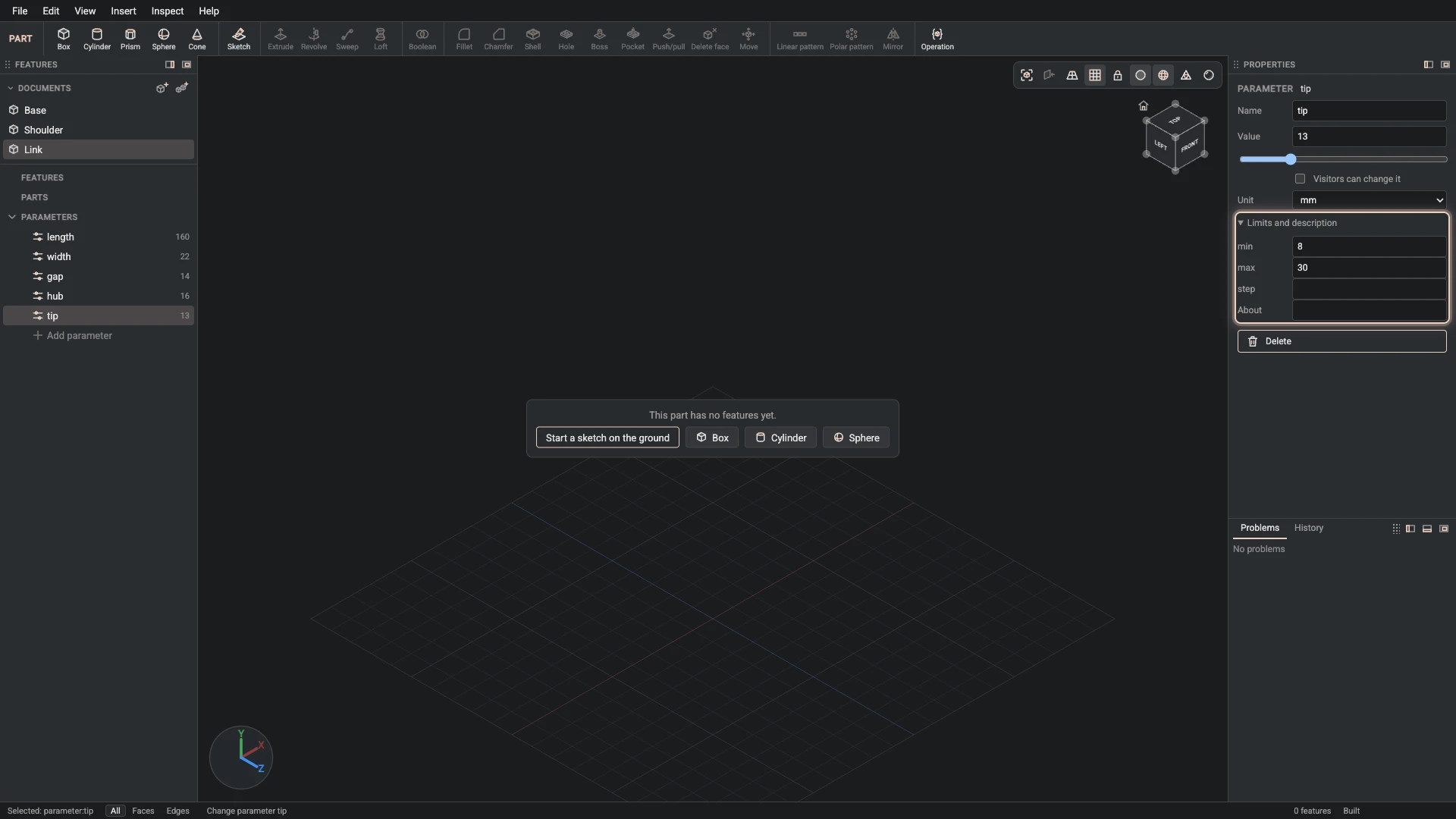
Change parameter, from the Properties panel: name tip, min 8, max 30.
Give tip its range, 8 to 30 mm: the values the design is drawn for.
-
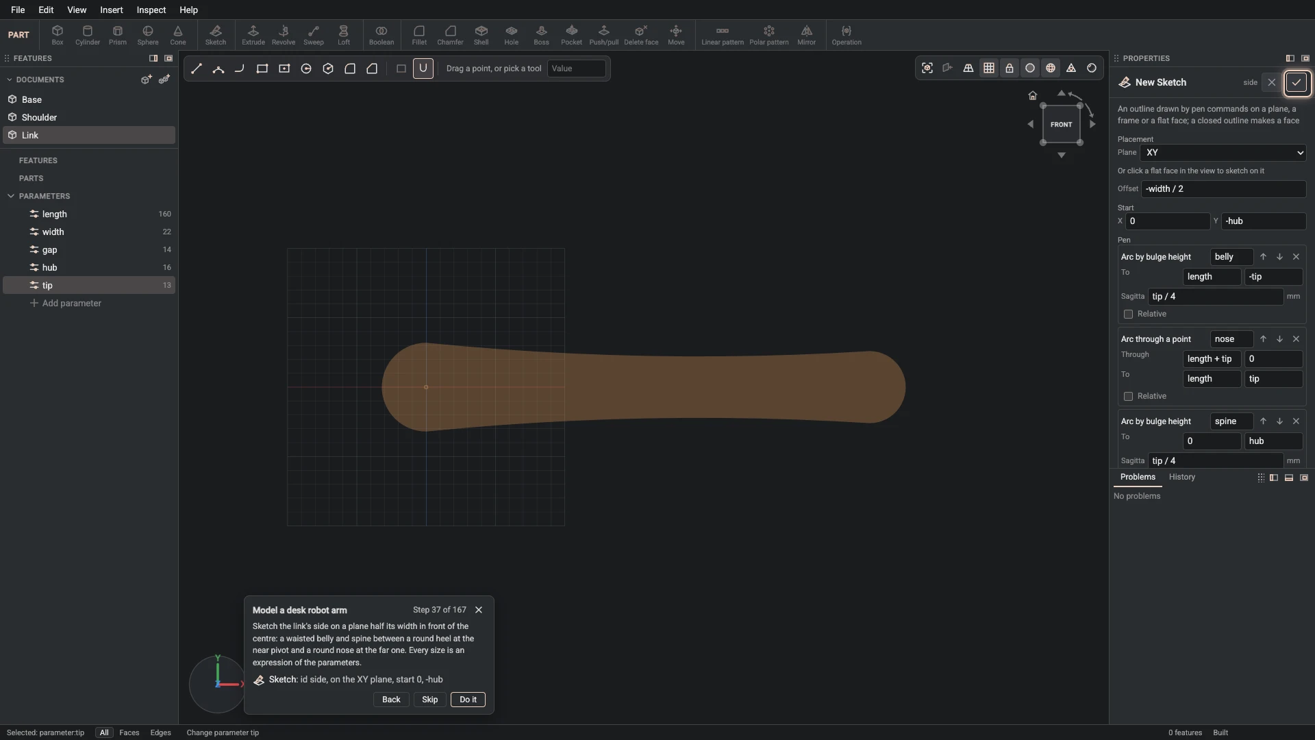
Sketch, from Insert > Sketch: id side, on the XY plane, start 0, -hub.
Sketch the link's side on a plane half its width in front of the centre: a waisted belly and spine between a round heel at the near pivot and a round nose at the far one. Every size is an expression of the parameters.
-
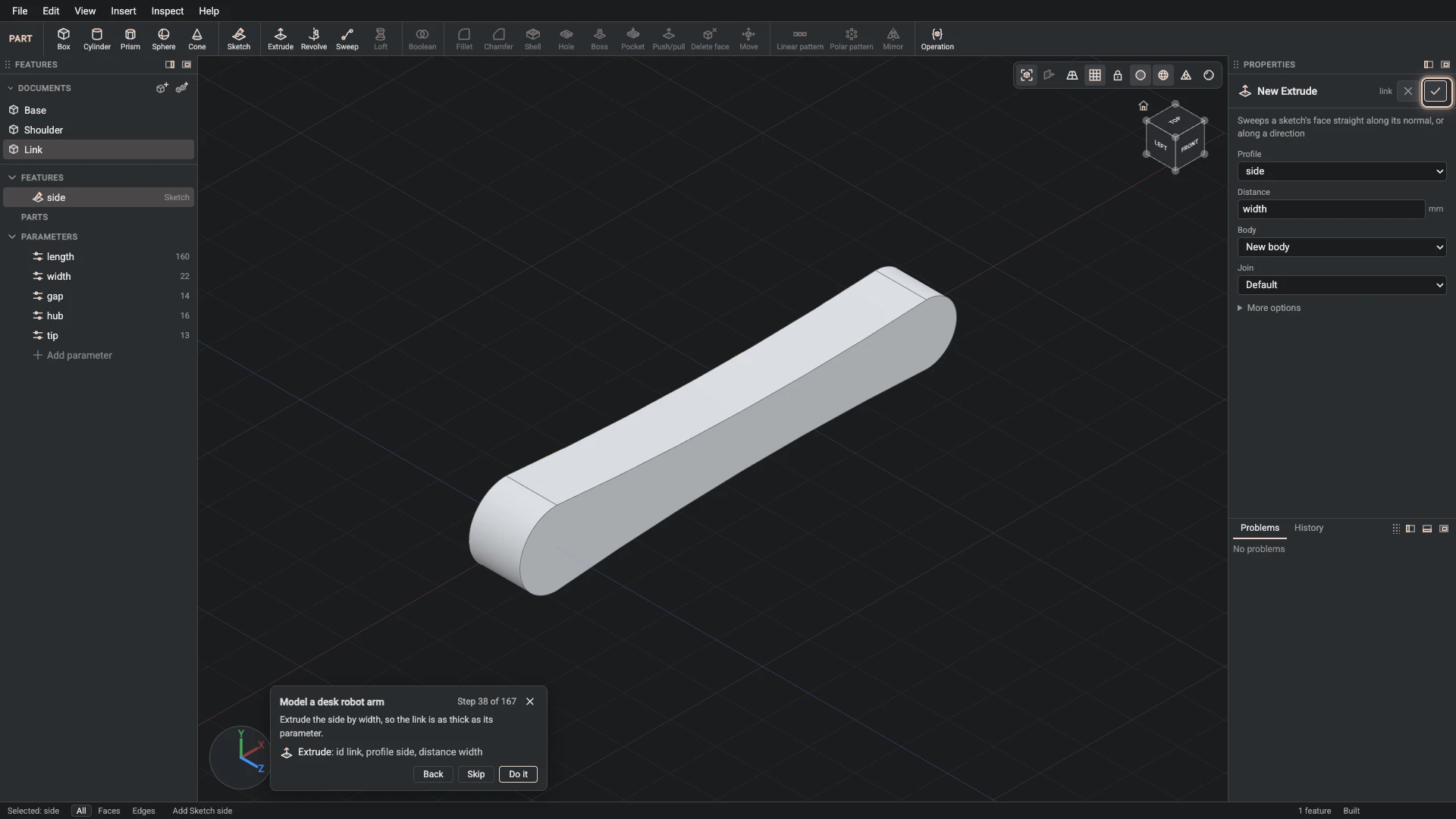
Extrude, from Insert > Extrude: id link, profile side, distance width.
Extrude the side by width, so the link is as thick as its parameter.
-
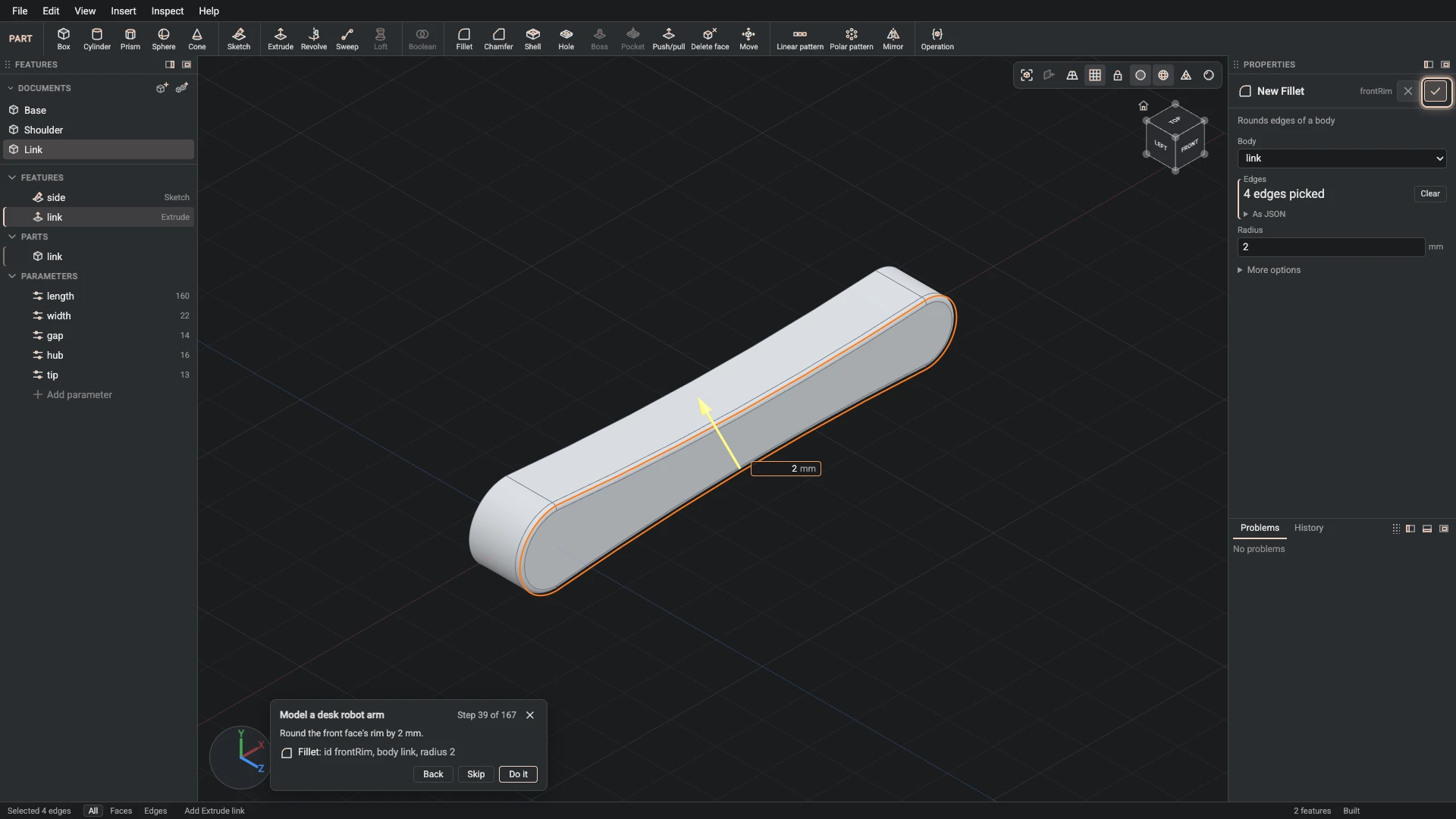
Fillet, from Insert > Fillet: id frontRim, body link, radius 2.
Round the front face's rim by 2 mm.
-
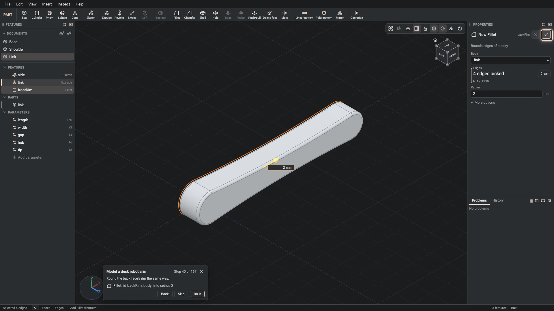
Fillet, from Insert > Fillet: id backRim, body link, radius 2.
Round the back face's rim the same way.
-
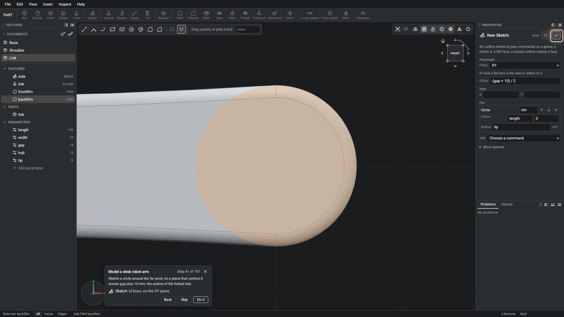
Sketch, from Insert > Sketch: id boss, on the XY plane.
Sketch a circle around the far pivot, on a plane that centres it across gap plus 10 mm: the outline of the forked hub.
-
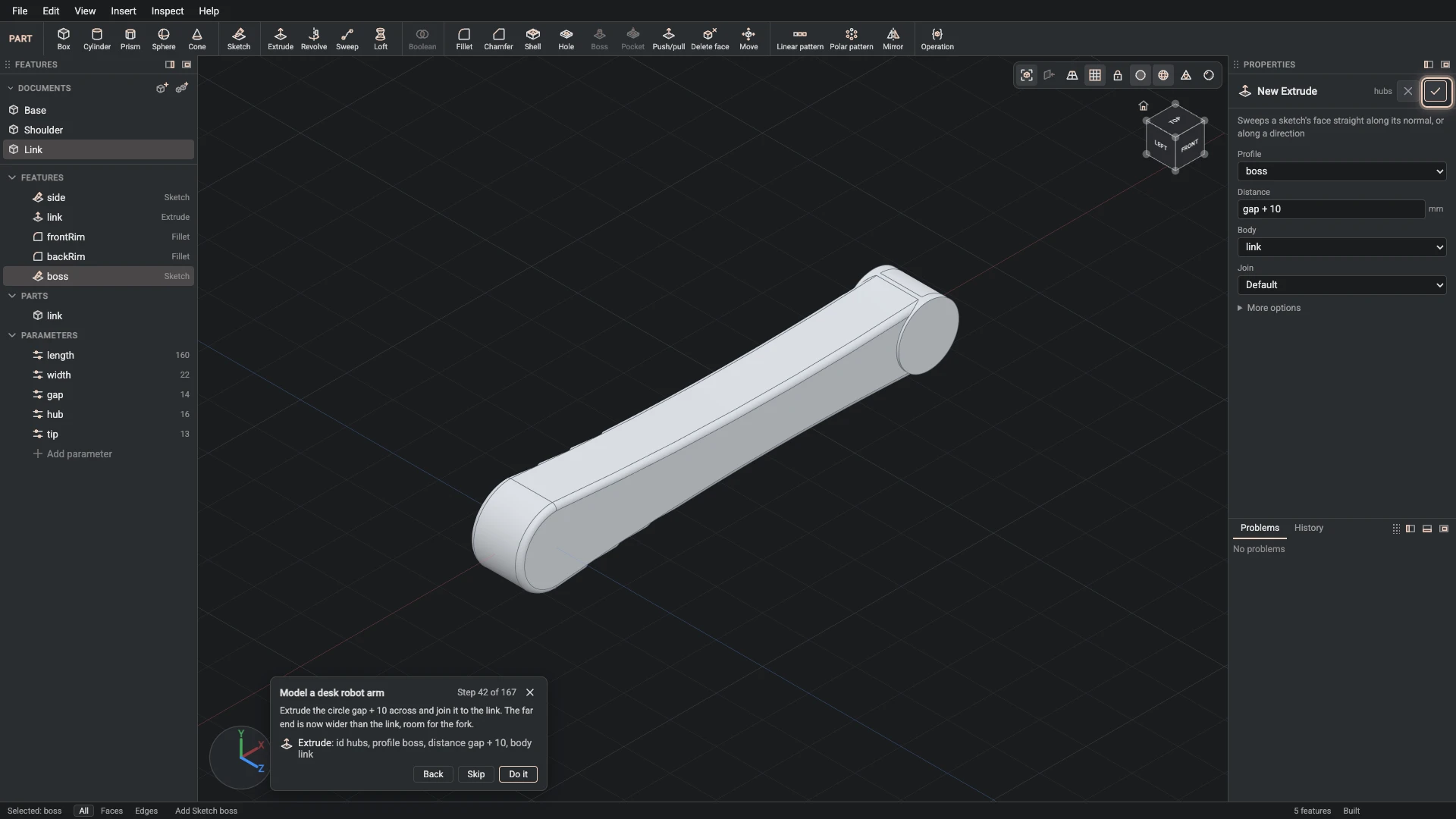
Extrude, from Insert > Extrude: id hubs, profile boss, distance gap + 10, body link.
Extrude the circle gap + 10 across and join it to the link. The far end is now wider than the link, room for the fork.
-
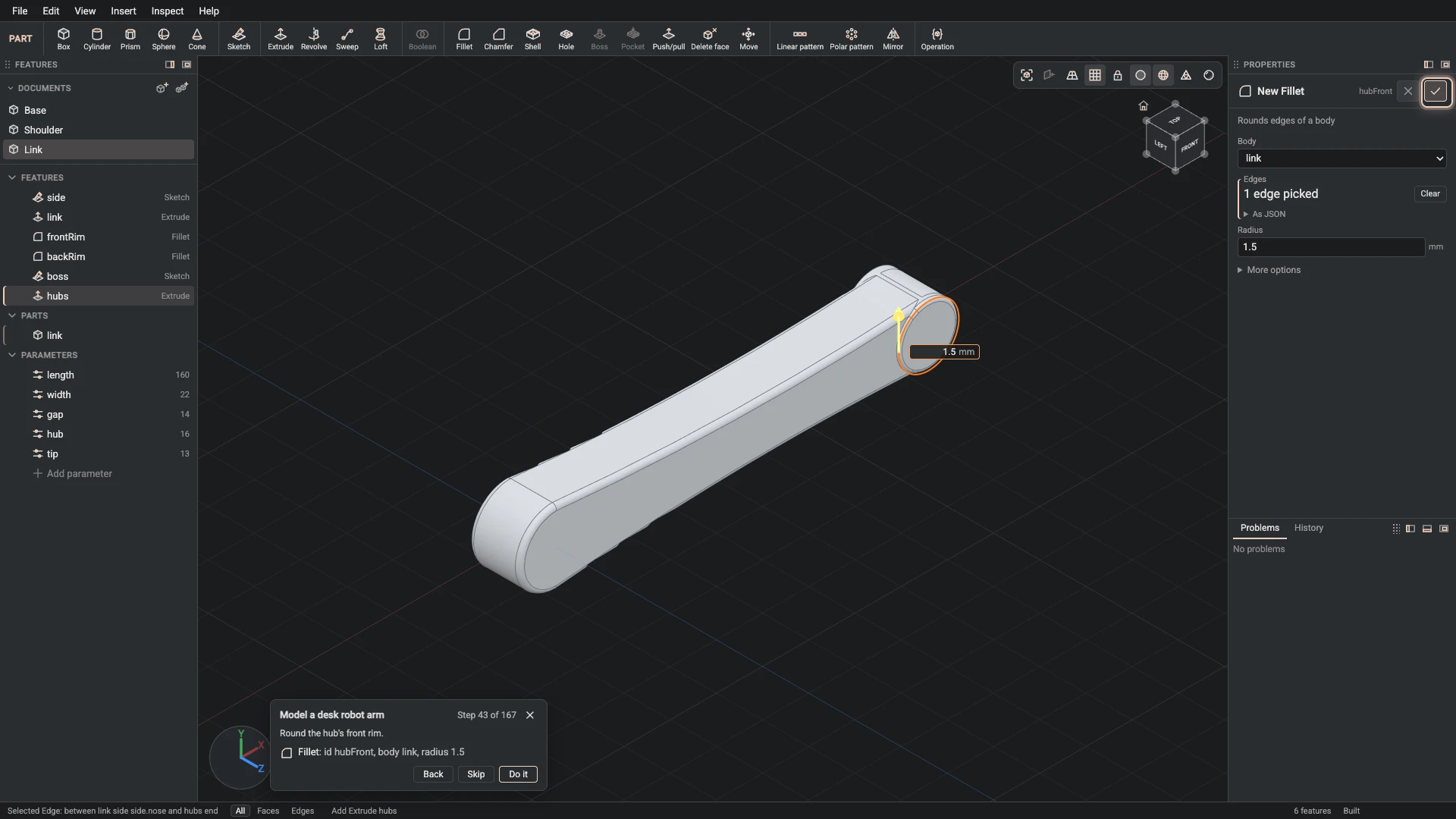
Fillet, from Insert > Fillet: id hubFront, body link, radius 1.5.
Round the hub's front rim.
-
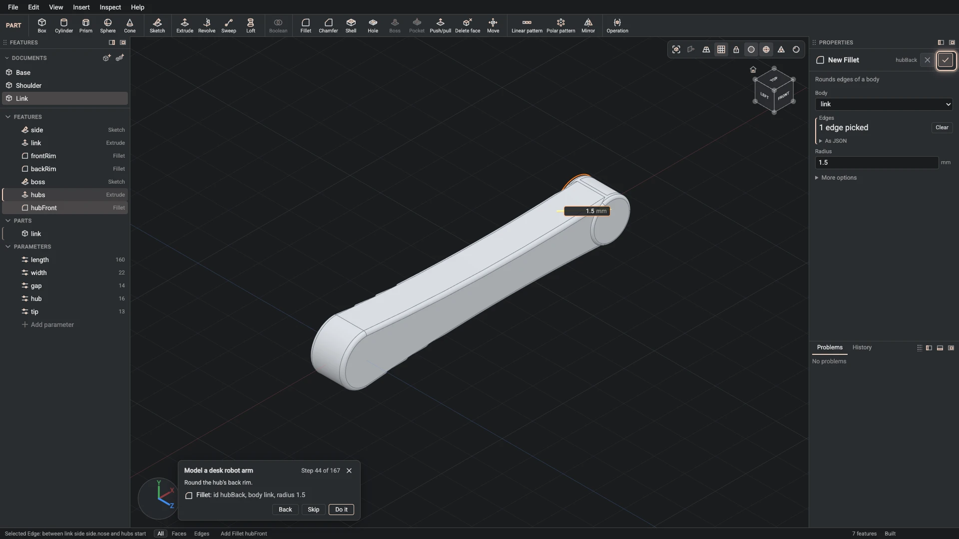
Fillet, from Insert > Fillet: id hubBack, body link, radius 1.5.
Round the hub's back rim.
-
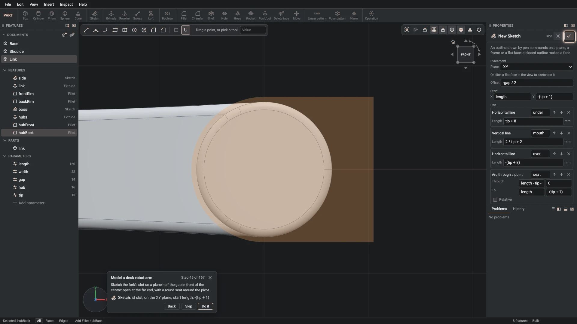
Sketch, from Insert > Sketch: id slot, on the XY plane, start length, -(tip + 1).
Sketch the fork's slot on a plane half the gap in front of the centre: open at the far end, with a round seat around the pivot.
-
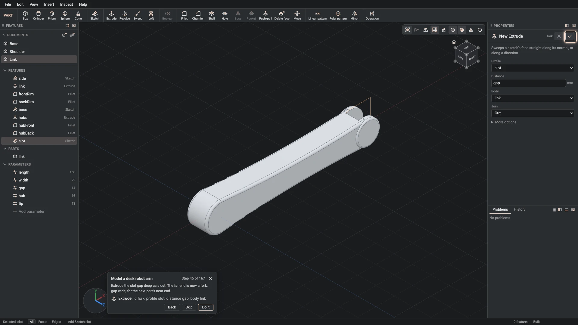
Extrude, from Insert > Extrude: id fork, profile slot, distance gap, body link, join cut.
Extrude the slot gap deep as a cut. The far end is now a fork, gap wide, for the next part's near end.
-
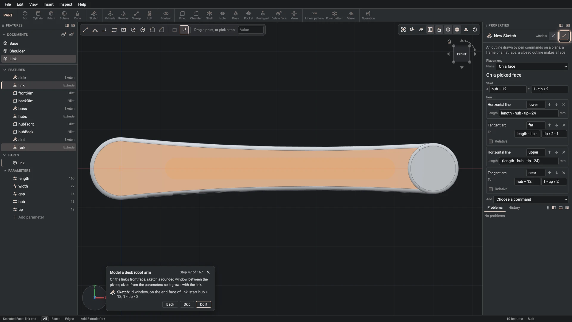
Sketch, from Insert > Sketch: id window, on the end face of link, start hub + 12, 1 - tip / 2.
On the link's front face, sketch a rounded window between the pivots, sized from the parameters so it grows with the link.
-
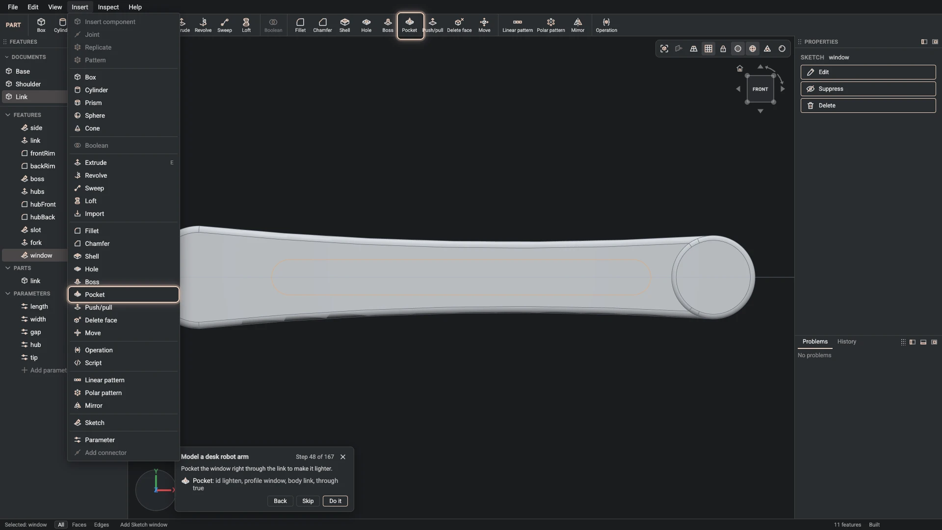
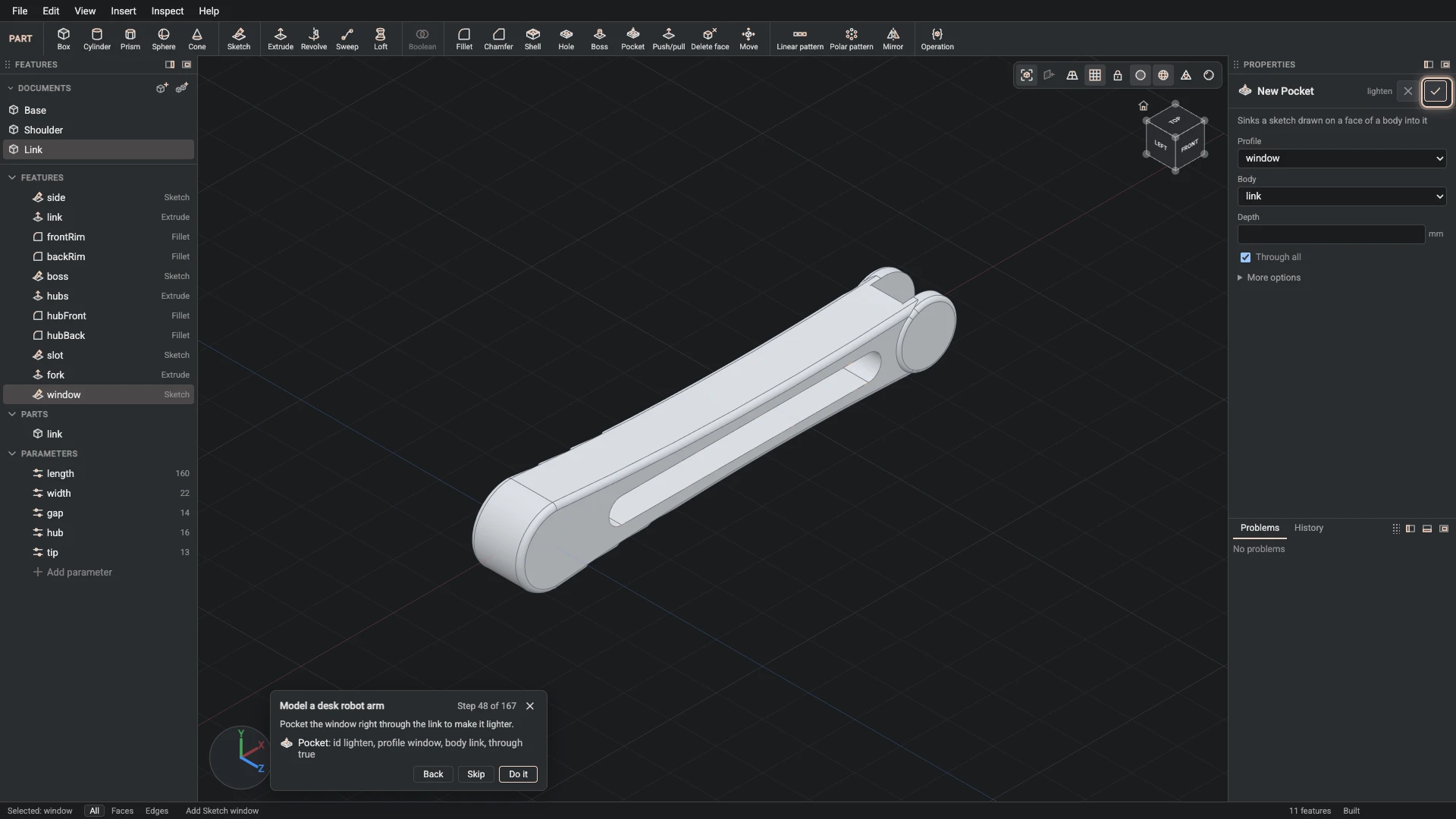
Pocket, from Insert > Pocket: id lighten, profile window, body link, through true.
Pocket the window right through the link to make it lighter.
-
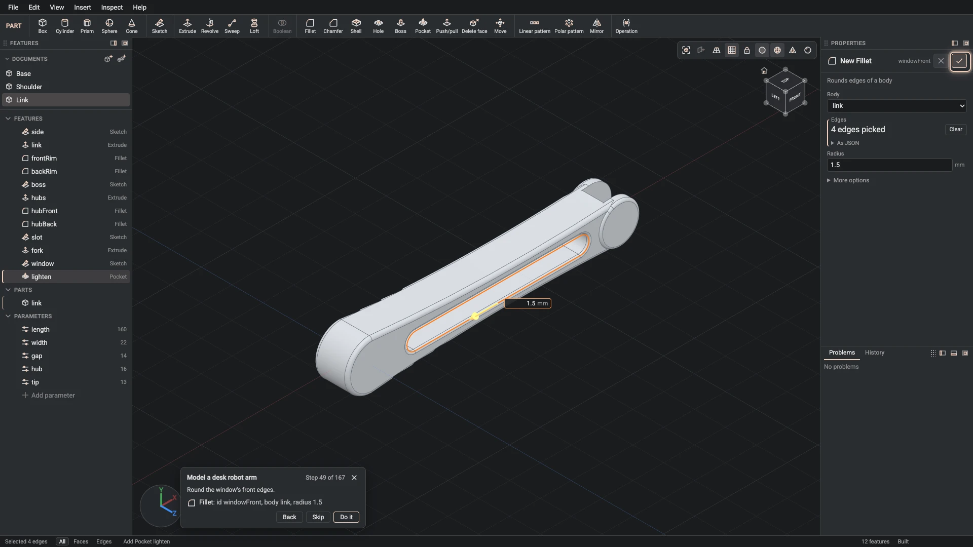
Fillet, from Insert > Fillet: id windowFront, body link, radius 1.5.
Round the window's front edges.
-
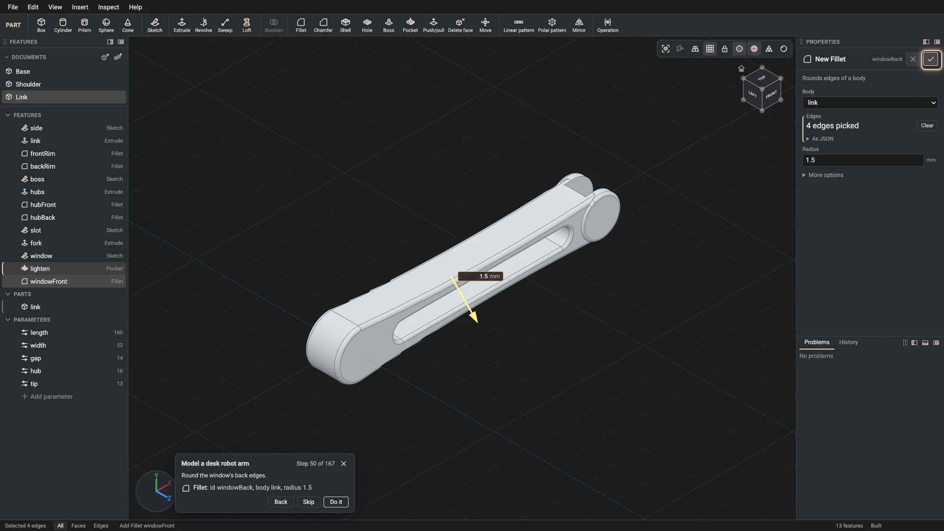
Fillet, from Insert > Fillet: id windowBack, body link, radius 1.5.
Round the window's back edges.
-
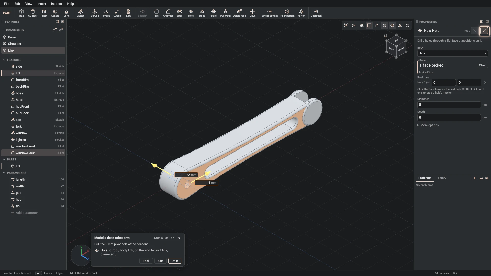
Hole, from Insert > Hole: id root, body link, on the end face of link, diameter 8.
Drill the 8 mm pivot hole at the near end.
-
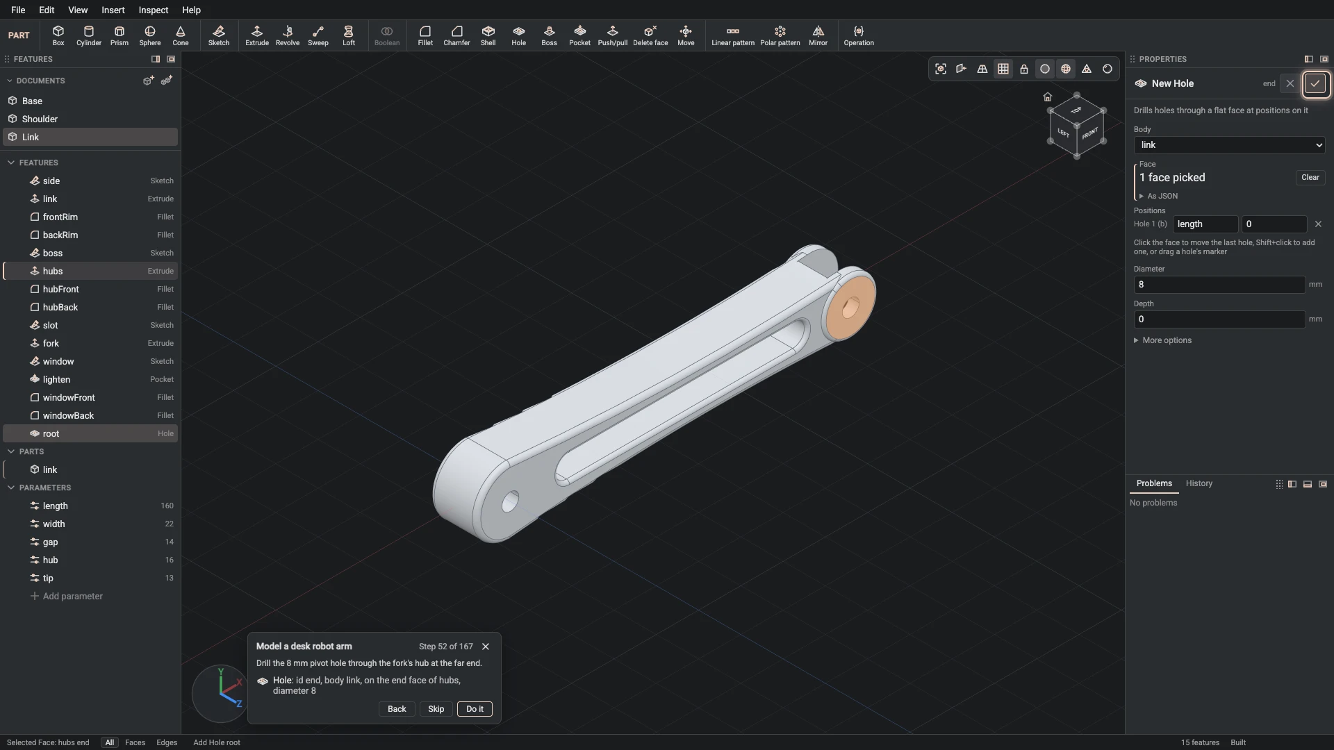
Hole, from Insert > Hole: id end, body link, on the end face of hubs, diameter 8.
Drill the 8 mm pivot hole through the fork's hub at the far end.
-
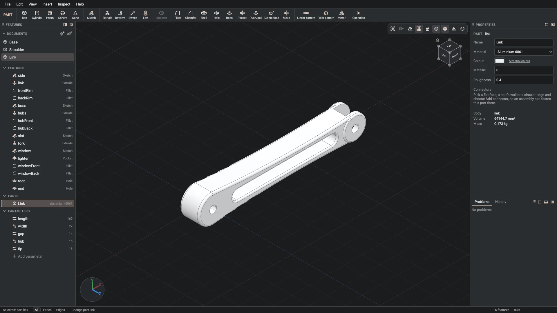
Part properties, from the Properties panel: id link, name Link, material aluminium-6061, color #eceef1, metallic 0, roughness 0.4.
Name the part Link: aluminium, painted white.
-
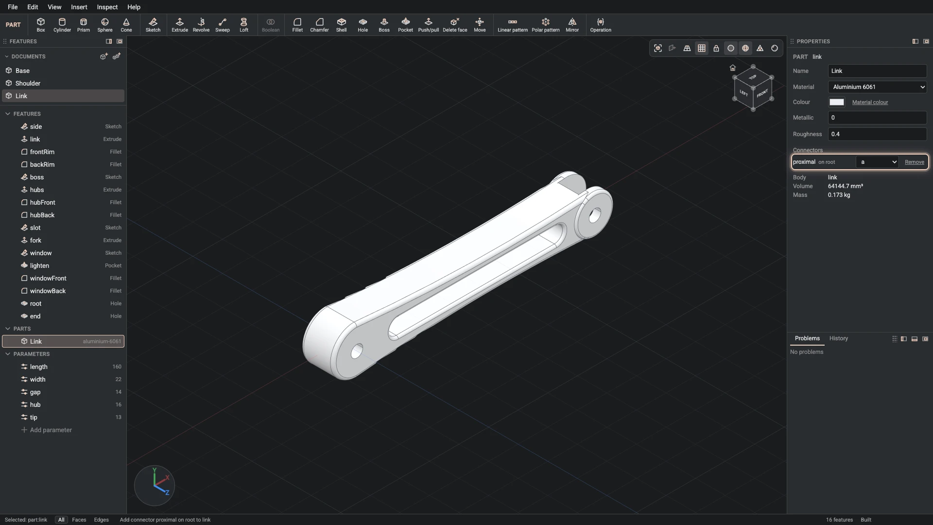
Add connector, from Insert > Add connector: part link, id proximal, on the start face of link, axis the wall face of root.
Add a connector at the near pivot, on the link's back face. The link turns about it on the part before.
-
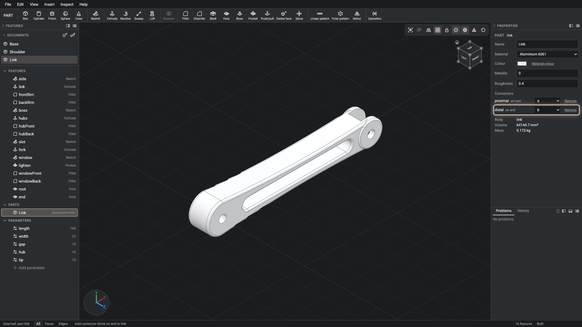
Add connector, from Insert > Add connector: part link, id distal, on the start face of fork, axis the wall face of end.
Add a connector at the far pivot, inside the fork. The next part turns about it.
-
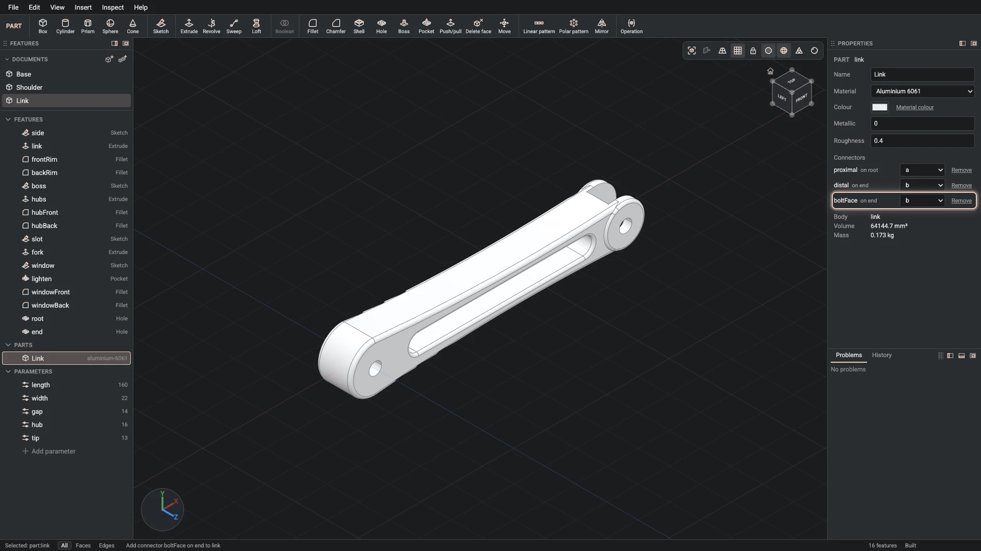
Add connector, from Insert > Add connector: part link, id boltFace, on the end face of hubs, axis the wall face of end.
Add a connector on the hub's front face, where the bolt's head sits.
-
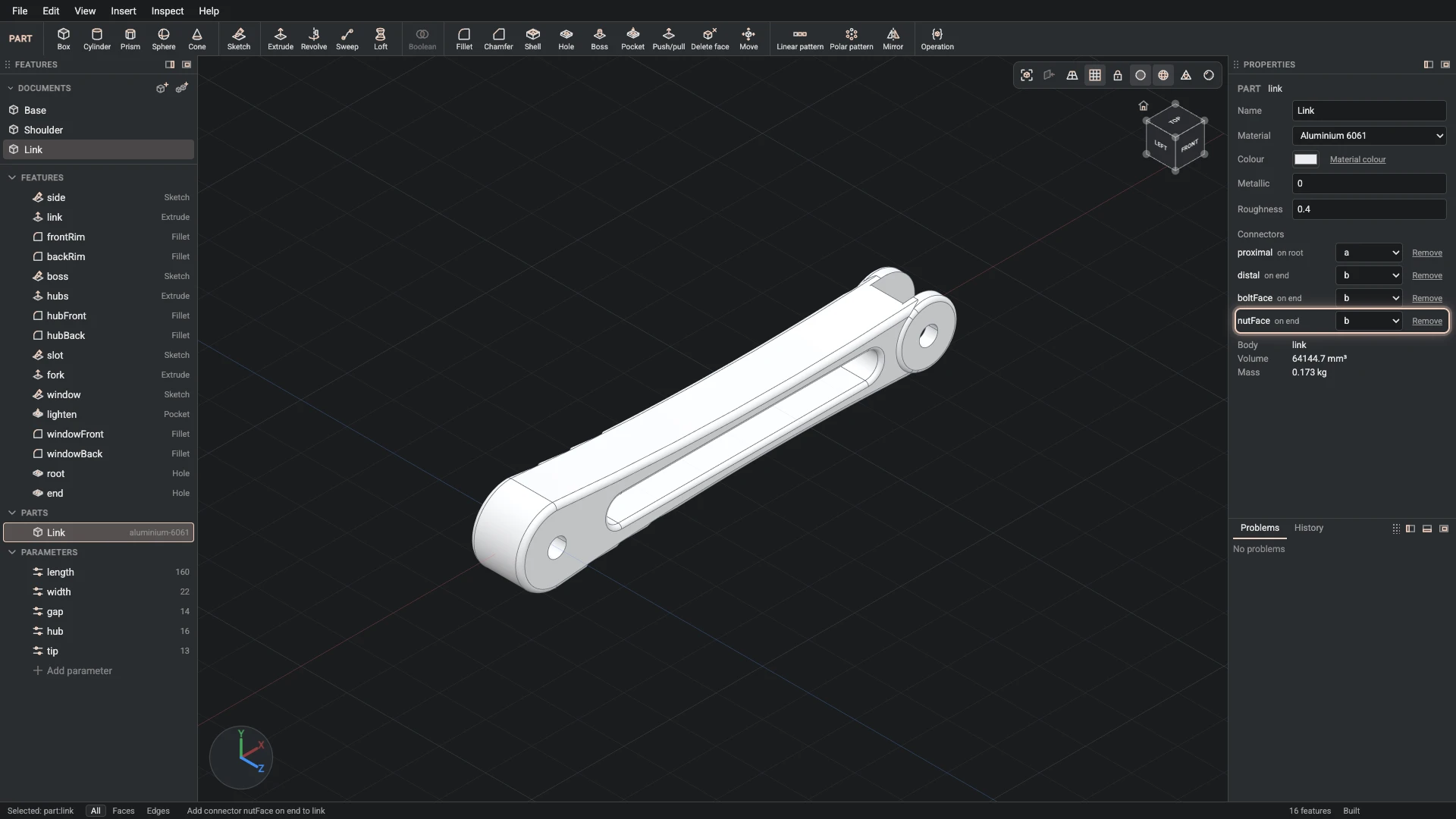
Add connector, from Insert > Add connector: part link, id nutFace, on the start face of hubs, axis the wall face of end.
Add a connector on the hub's back face, where the nut goes.
Verified against the product in October 2026