Model a desk robot arm: the jaw
One jaw document makes both jaws. Its teeth are part of its outline, so they come from a single sketch rather than a pattern.
Each step shows the Designer as you make it: a feature's dialog filled in with the step's values, with the tutorial card ringing OK, or what the step made. The first time a command appears, a picture shows where it is. The step numbers match the card's in Help > Tutorials.
-
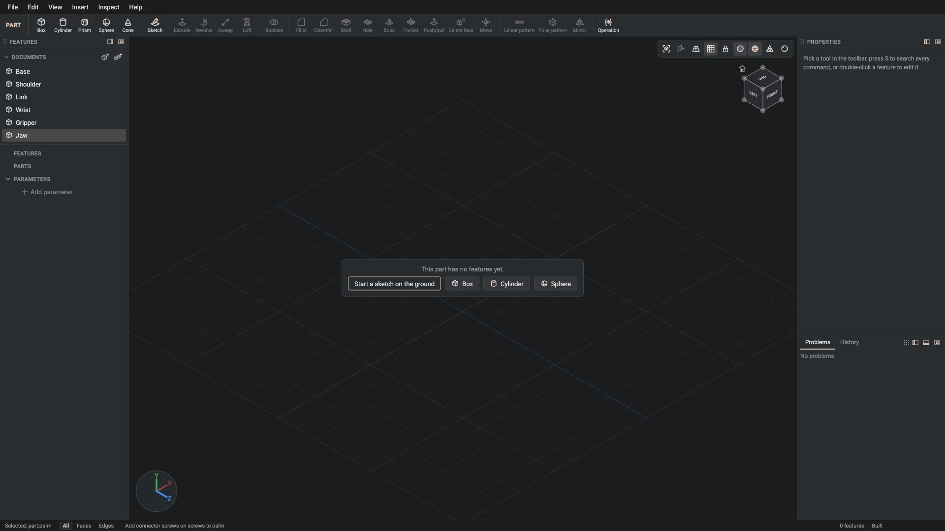
New part, from File > New part: name Jaw.
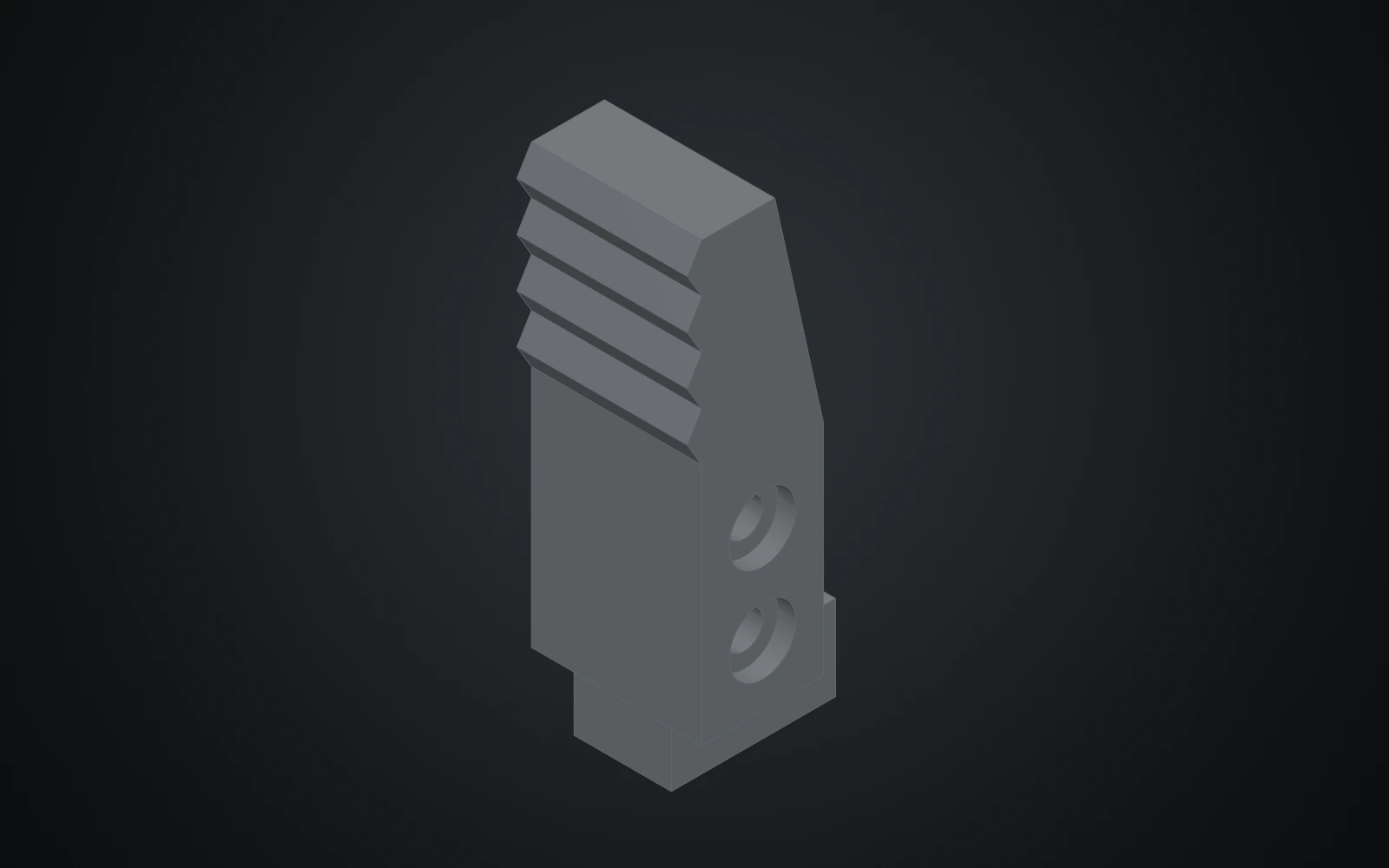
Each jaw is a serrated finger on a carriage that rides in the gripper's rail, held by two screws.
-
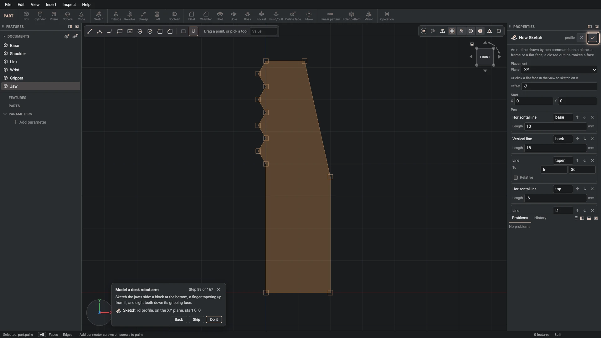
Sketch, from Insert > Sketch: id profile, on the XY plane, start 0, 0.
Sketch the jaw's side: a block at the bottom, a finger tapering up from it, and eight teeth down its gripping face.
-
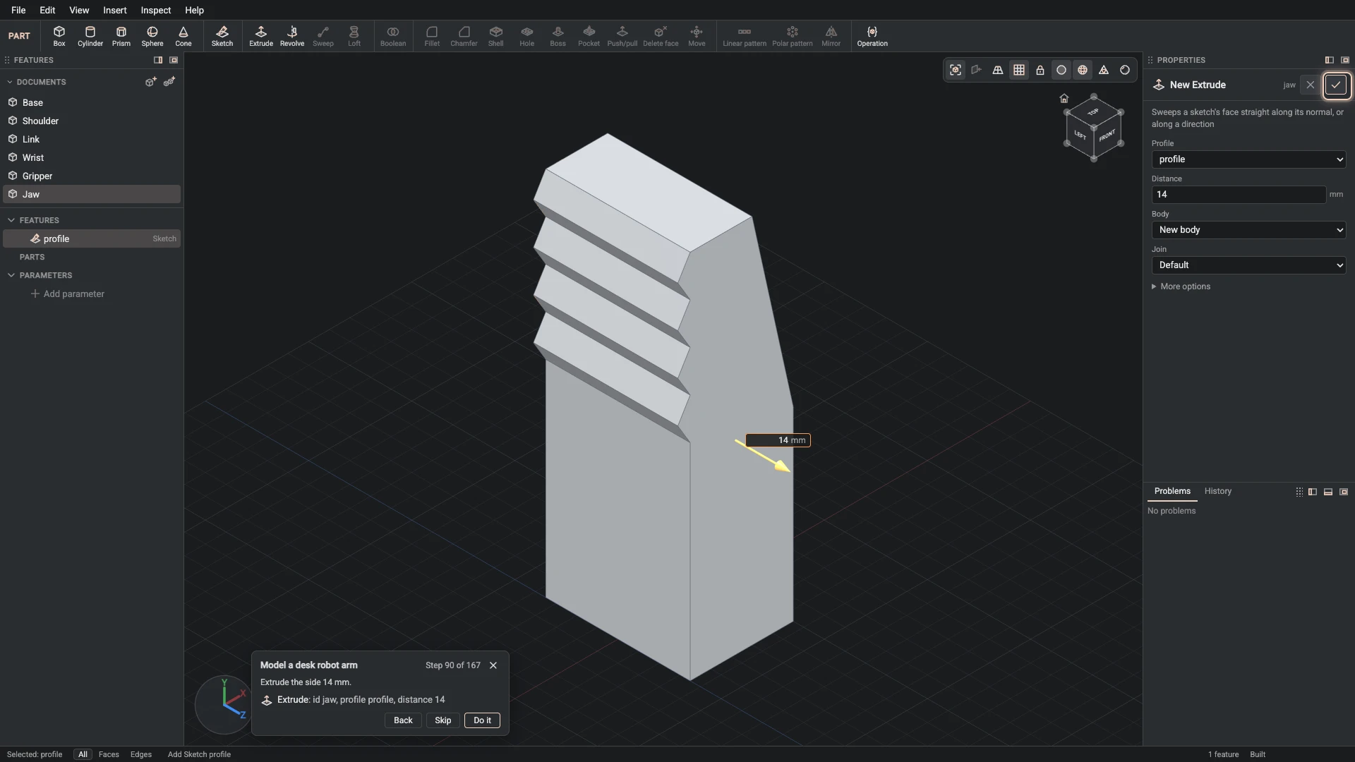
Extrude, from Insert > Extrude: id jaw, profile profile, distance 14.
Extrude the side 14 mm.
-
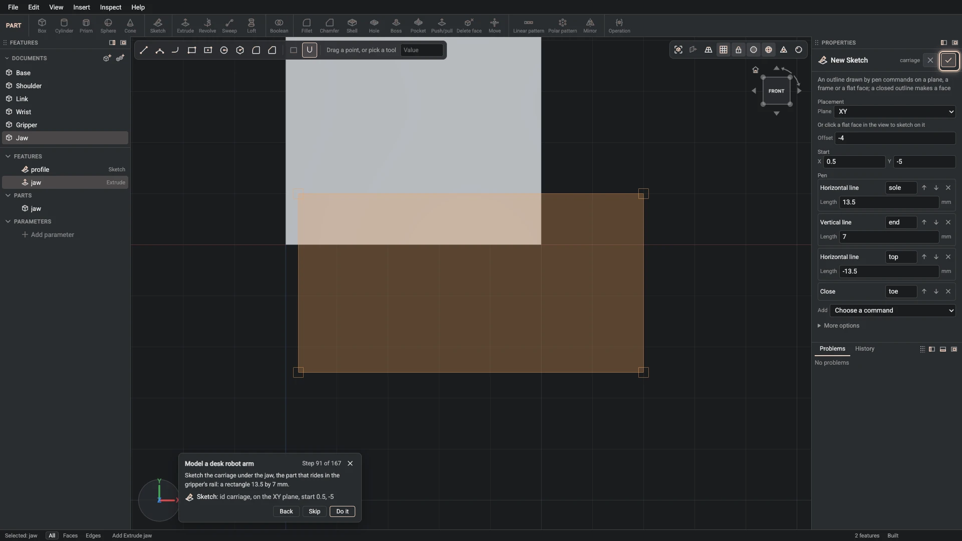
Sketch, from Insert > Sketch: id carriage, on the XY plane, start 0.5, -5.
Sketch the carriage under the jaw, the part that rides in the gripper's rail: a rectangle 13.5 by 7 mm.
-
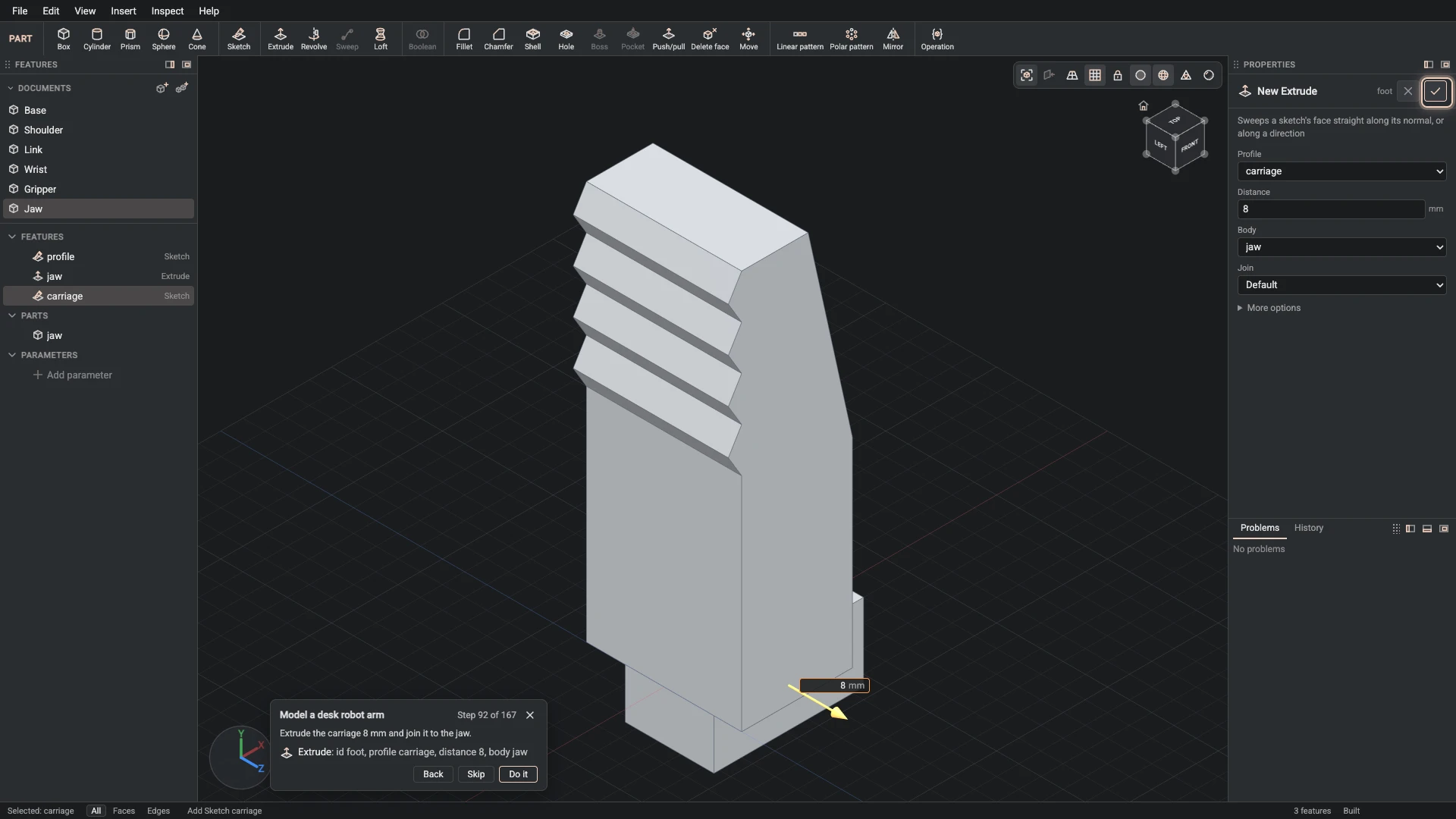
Extrude, from Insert > Extrude: id foot, profile carriage, distance 8, body jaw.
Extrude the carriage 8 mm and join it to the jaw.
-
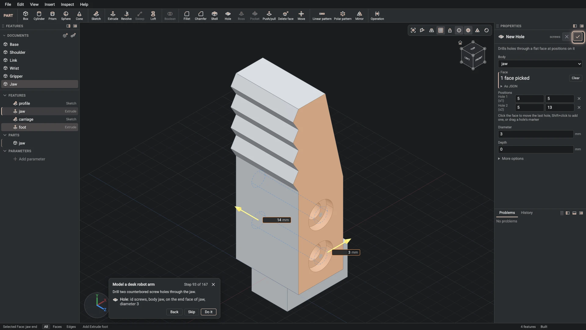
Hole, from Insert > Hole: id screws, body jaw, on the end face of jaw, diameter 3.
Drill two counterbored screw holes through the jaw.
-
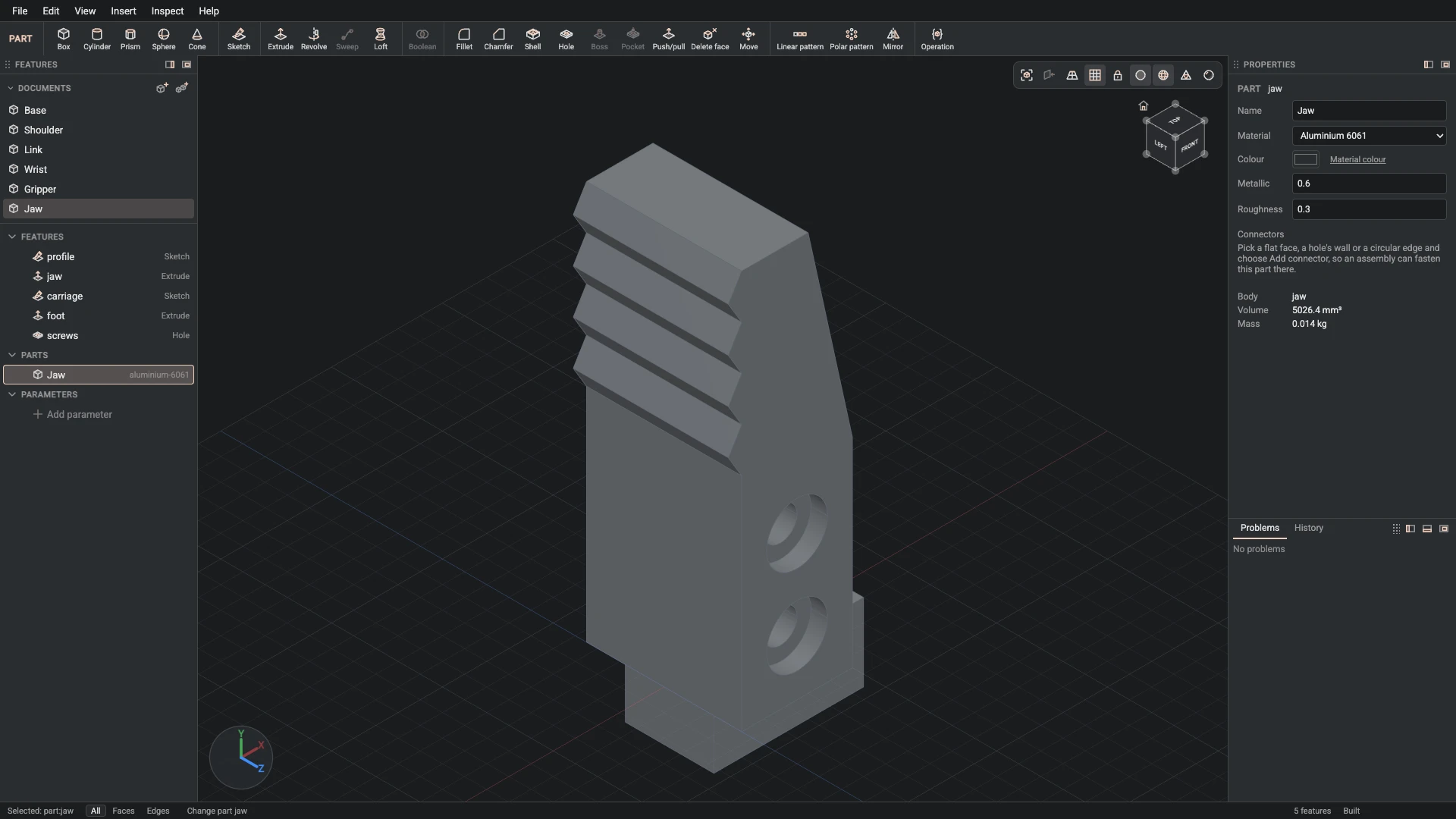
Part properties, from the Properties panel: id jaw, name Jaw, material aluminium-6061, color #2a2d31, metallic 0.6, roughness 0.3.
Name the part Jaw: dark anodised aluminium.
-
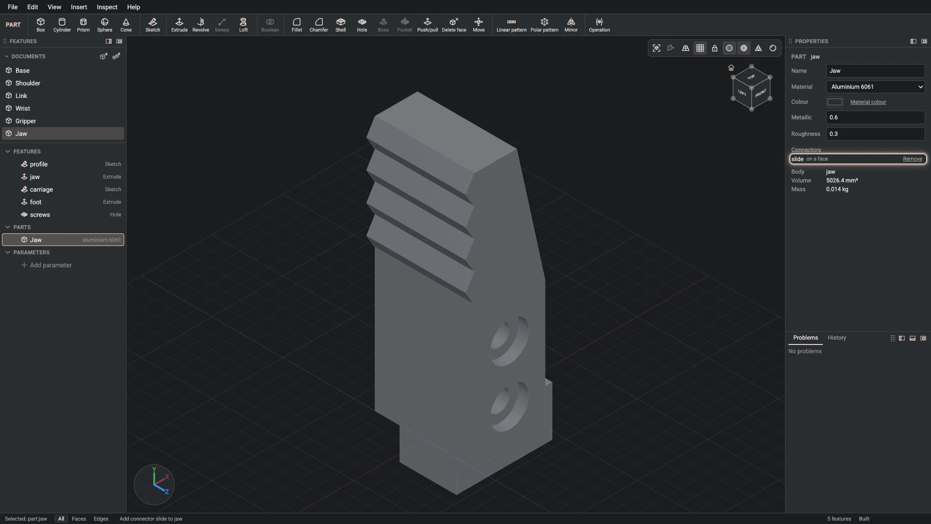
Add connector, from Insert > Add connector: part jaw, id slide, on the side face of foot.
Add a connector on the carriage's end. The jaw slides along the gripper's rail on it.
-
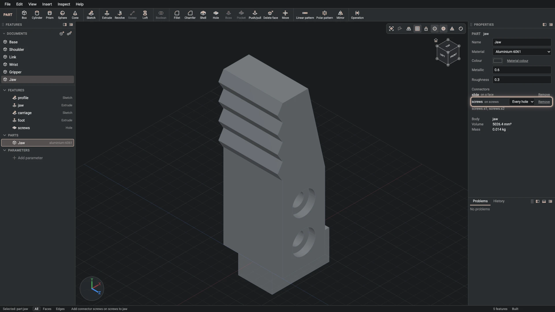
Add connector, from Insert > Add connector: part jaw, id screws, on the end face of jaw, axis the wall face of screws.
Add a connector on the jaw's face, its axis along the screw holes.
Verified against the product in October 2026