Model a desk robot arm: the gripper
The gripper's palm carries the jaws in two rails. Pockets cut the rails, and a fillet blends the neck into the palm so the two read as one cast piece.
Each step shows the Designer as you make it: a feature's dialog filled in with the step's values, with the tutorial card ringing OK, or what the step made. The first time a command appears, a picture shows where it is. The step numbers match the card's in Help > Tutorials.
-
New part, from File > New part: name Gripper.
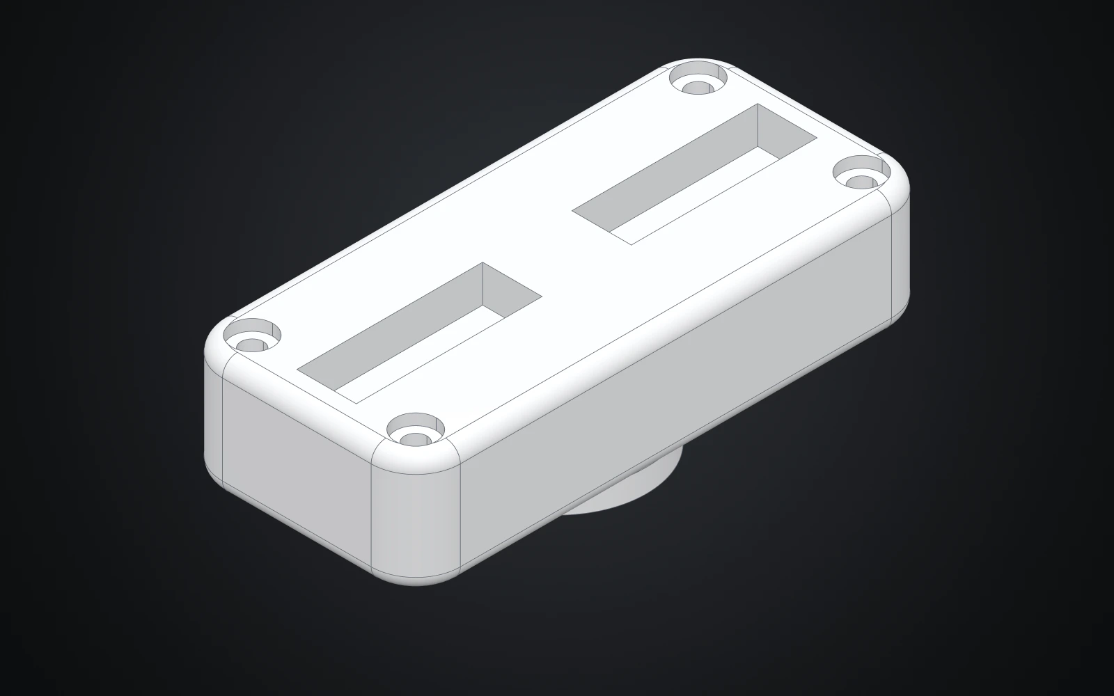
The gripper housing carries two jaw rails, four cover screws and a neck that is blended into the palm.
-
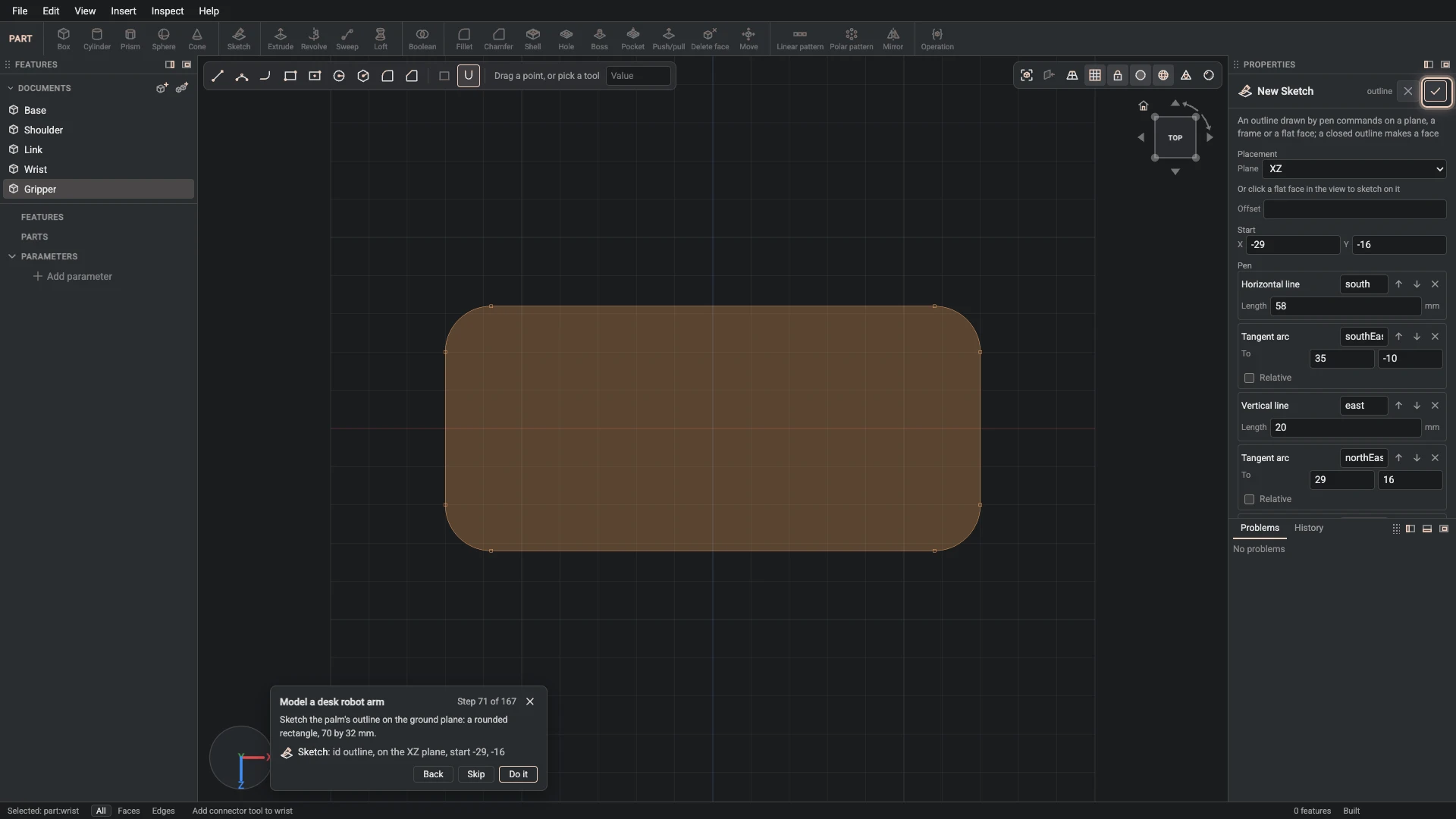
Sketch, from Insert > Sketch: id outline, on the XZ plane, start -29, -16.
Sketch the palm's outline on the ground plane: a rounded rectangle, 70 by 32 mm.
-
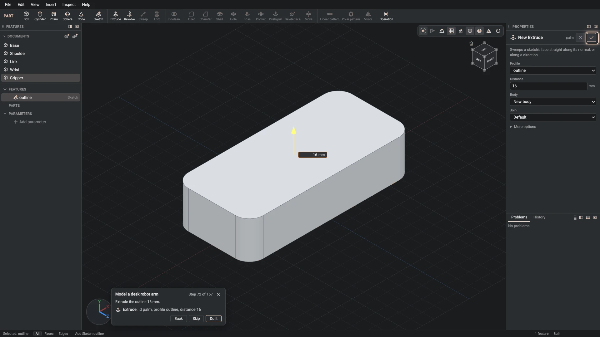
Extrude, from Insert > Extrude: id palm, profile outline, distance 16.
Extrude the outline 16 mm.
-
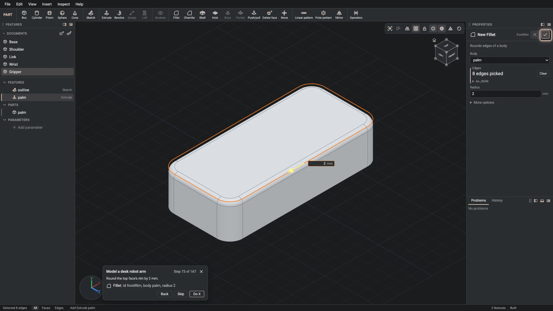
Fillet, from Insert > Fillet: id frontRim, body palm, radius 2.
Round the top face's rim by 2 mm.
-
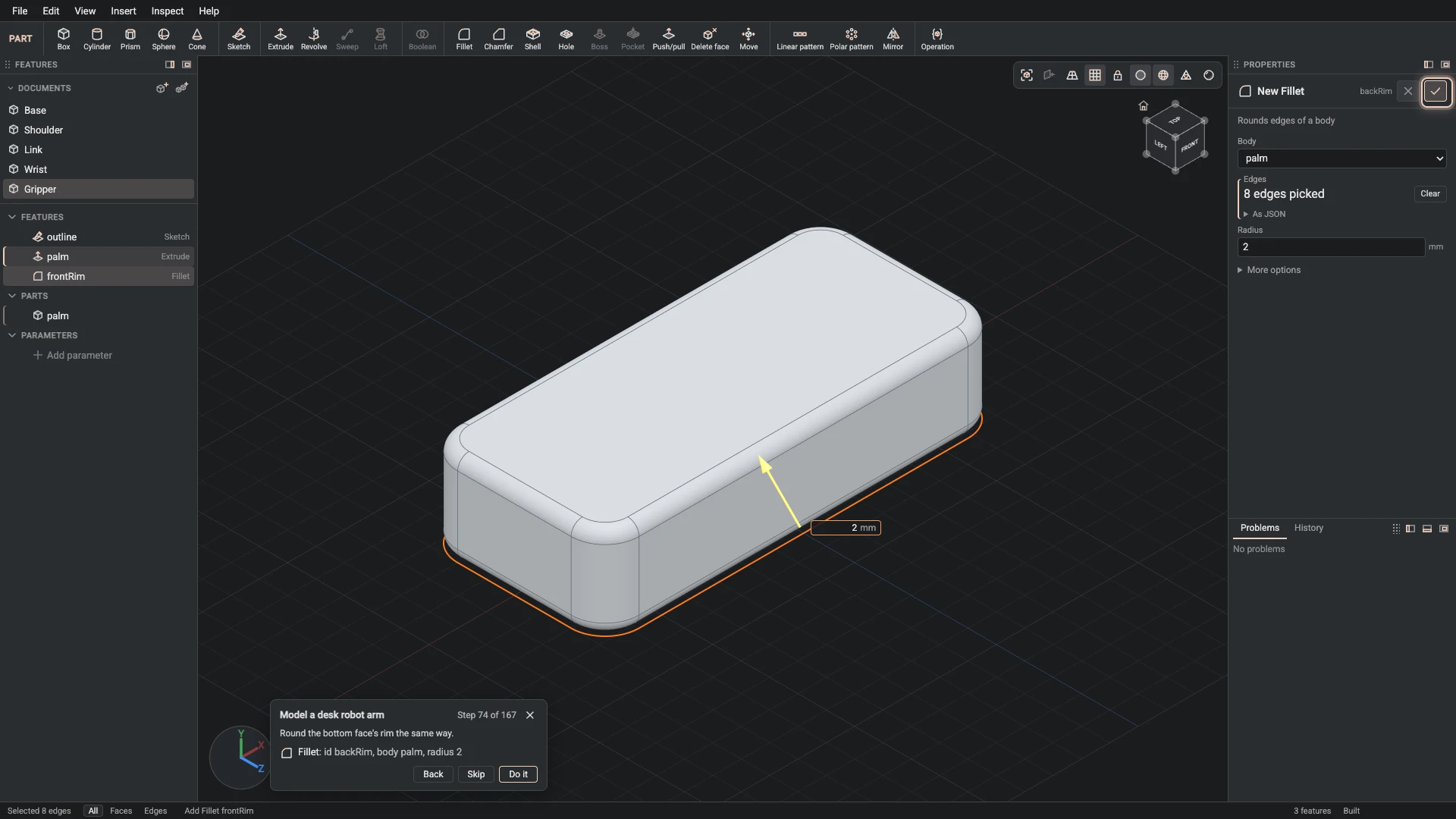
Fillet, from Insert > Fillet: id backRim, body palm, radius 2.
Round the bottom face's rim the same way.
-
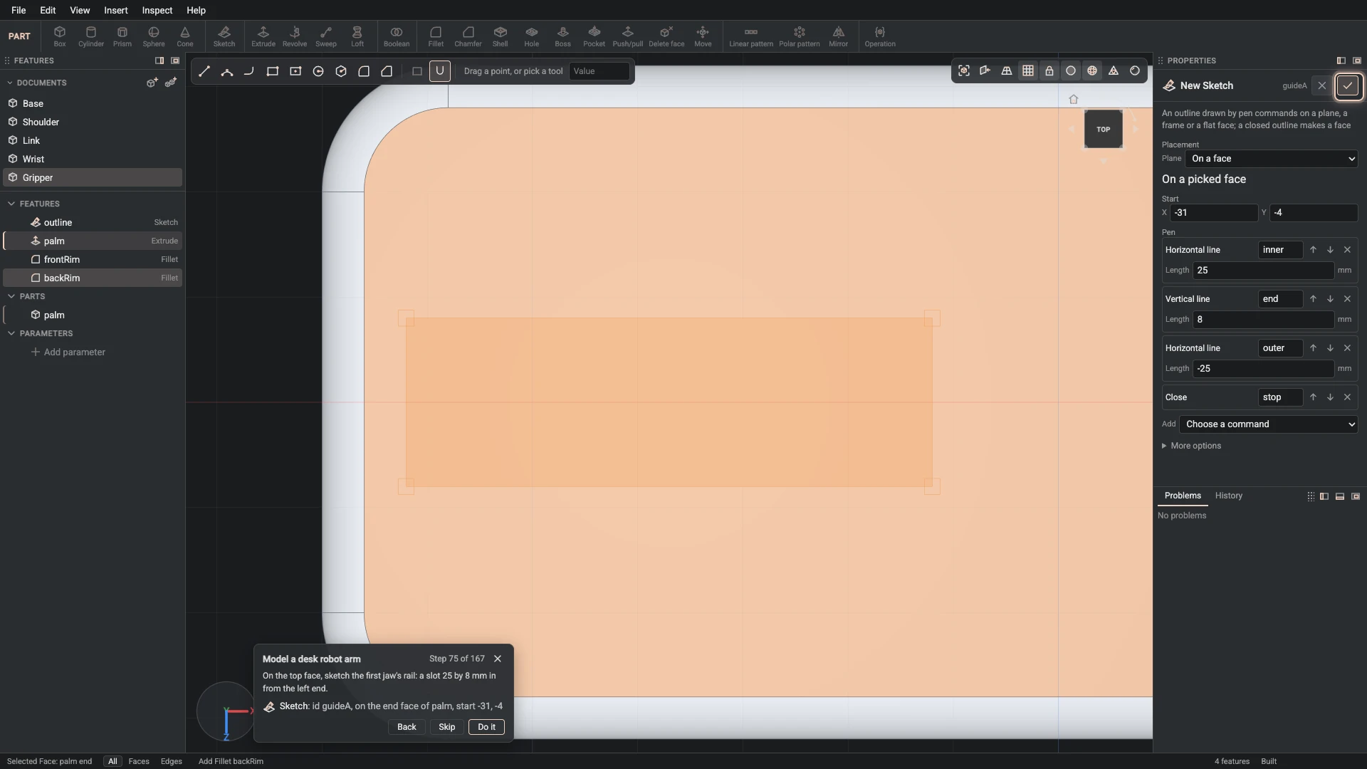
Sketch, from Insert > Sketch: id guideA, on the end face of palm, start -31, -4.
On the top face, sketch the first jaw's rail: a slot 25 by 8 mm in from the left end.
-
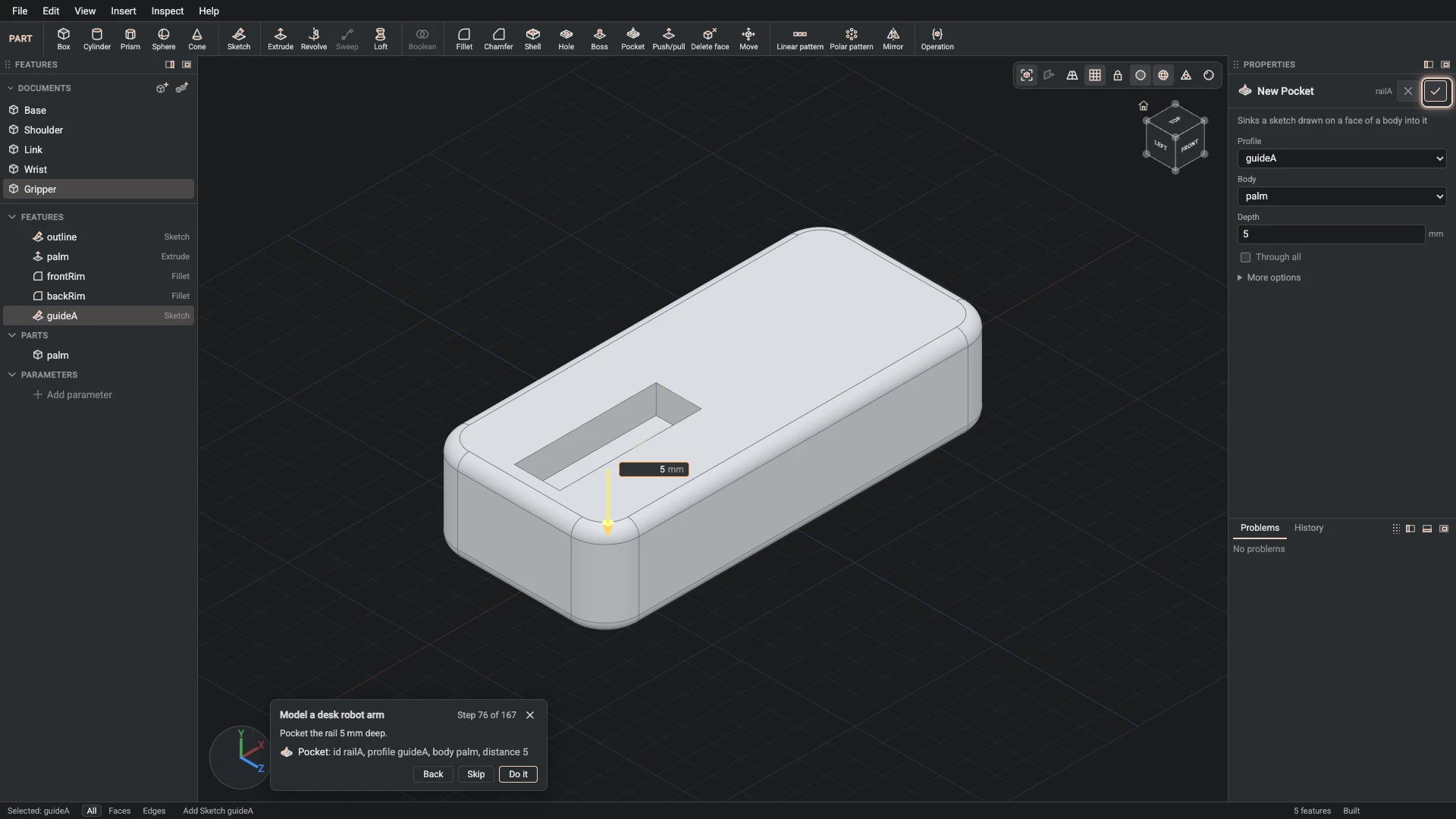
Pocket, from Insert > Pocket: id railA, profile guideA, body palm, distance 5.
Pocket the rail 5 mm deep.
-
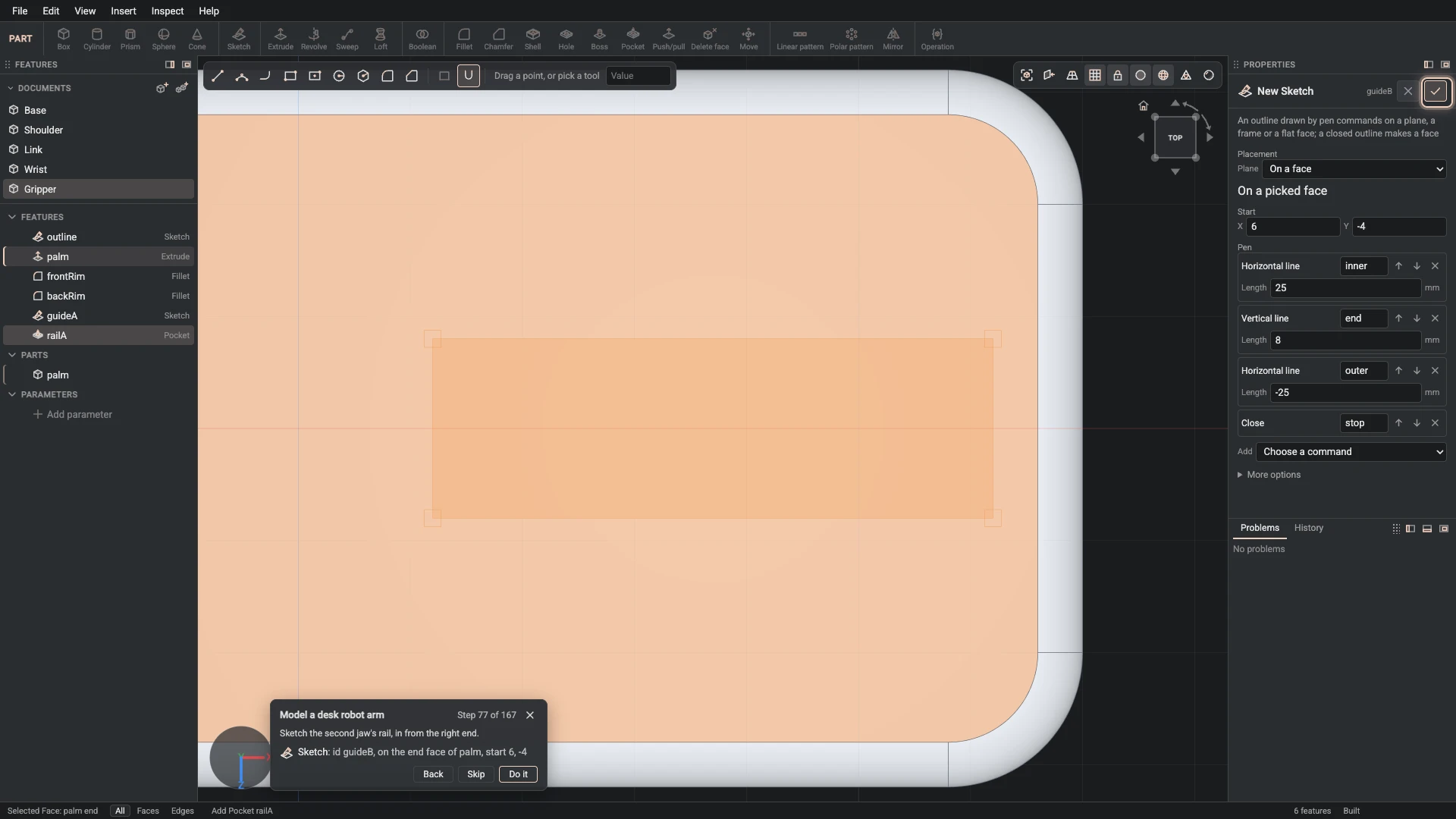
Sketch, from Insert > Sketch: id guideB, on the end face of palm, start 6, -4.
Sketch the second jaw's rail, in from the right end.
-
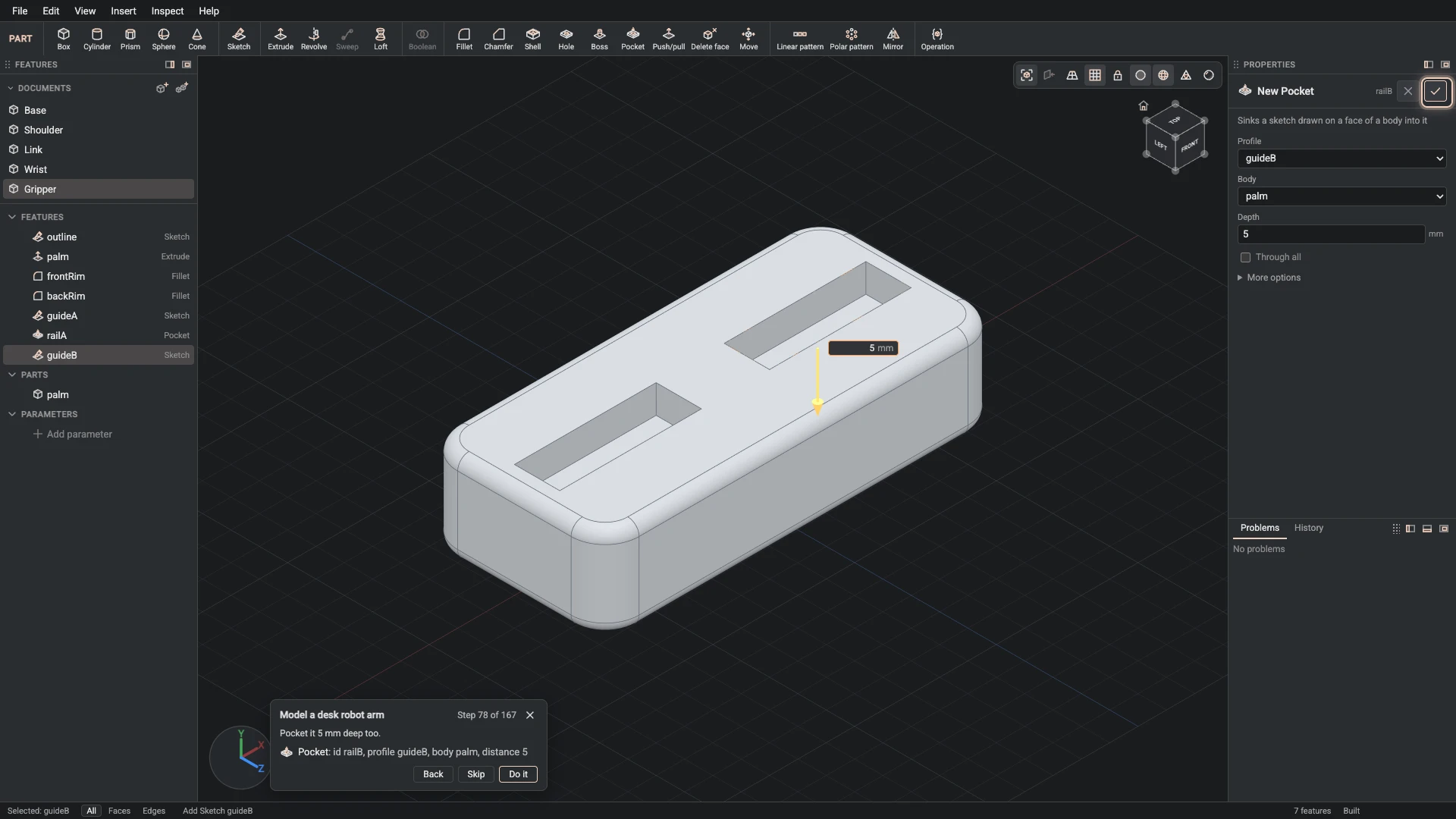
Pocket, from Insert > Pocket: id railB, profile guideB, body palm, distance 5.
Pocket it 5 mm deep too.
-
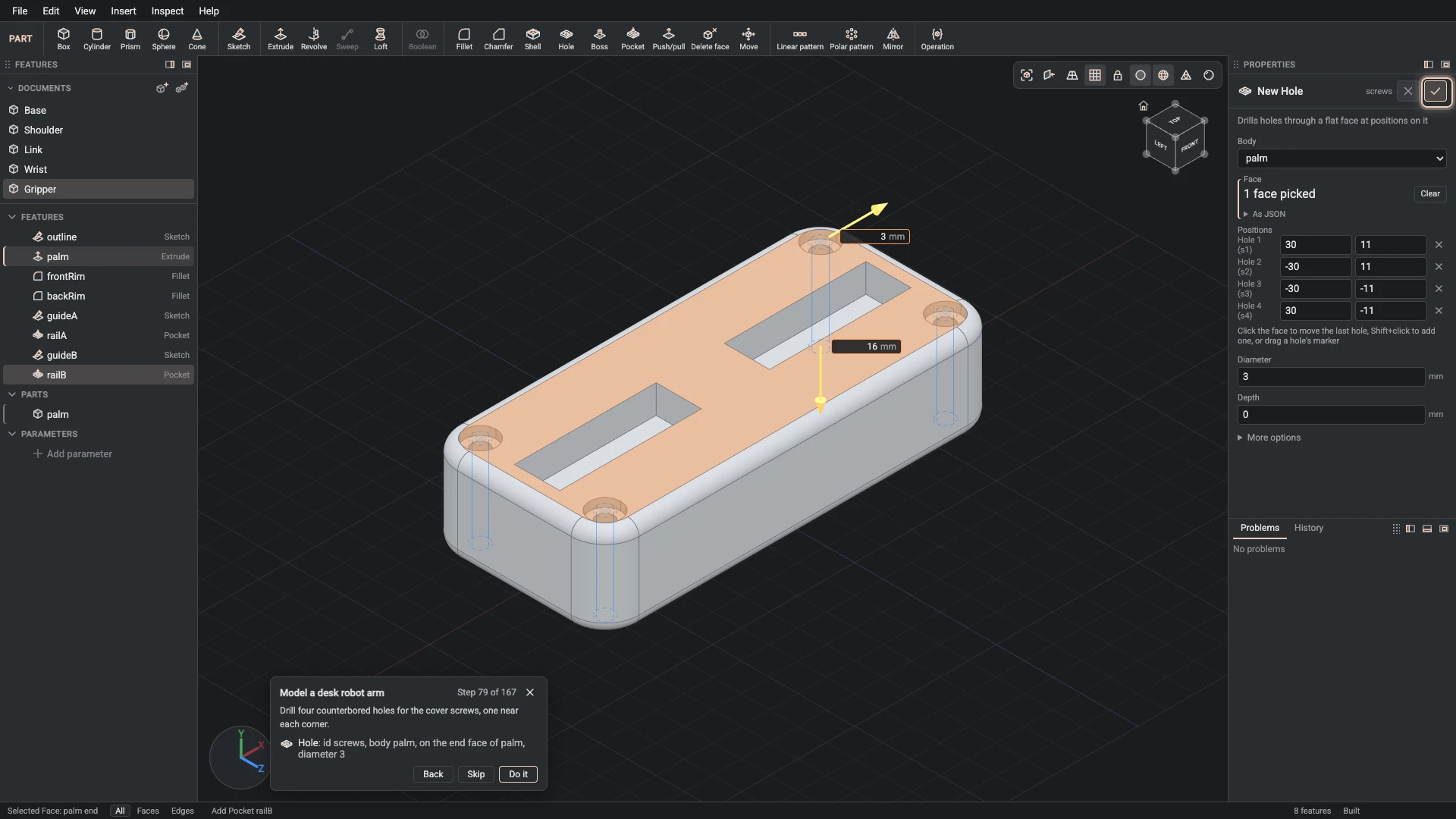
Hole, from Insert > Hole: id screws, body palm, on the end face of palm, diameter 3.
Drill four counterbored holes for the cover screws, one near each corner.
-
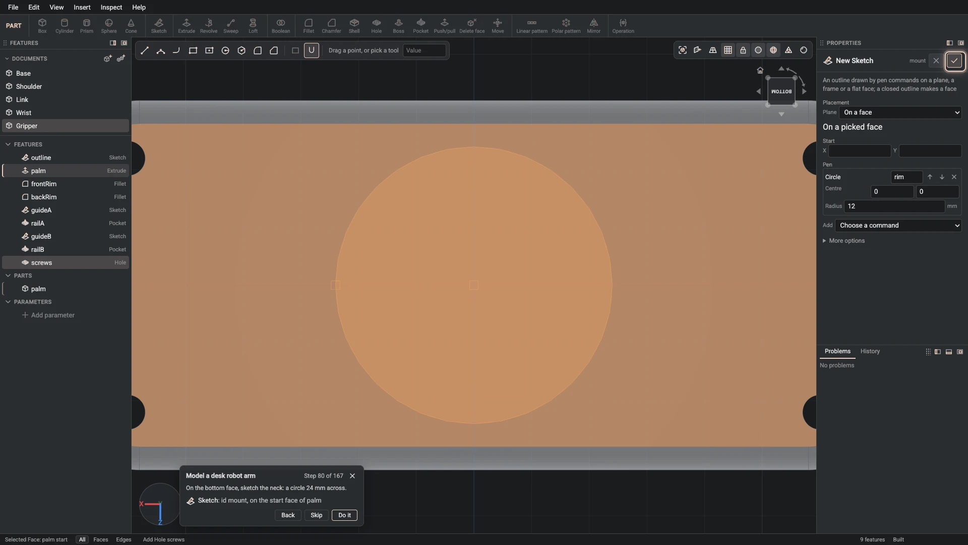
Sketch, from Insert > Sketch: id mount, on the start face of palm.
On the bottom face, sketch the neck: a circle 24 mm across.
-
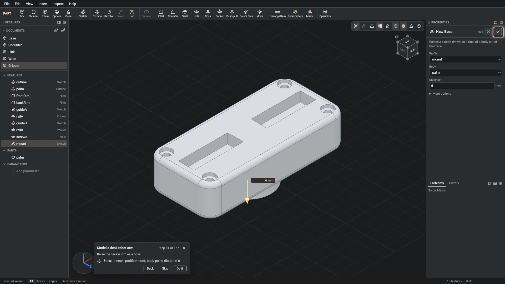
Boss, from Insert > Boss: id neck, profile mount, body palm, distance 6.
Raise the neck 6 mm as a boss.
-
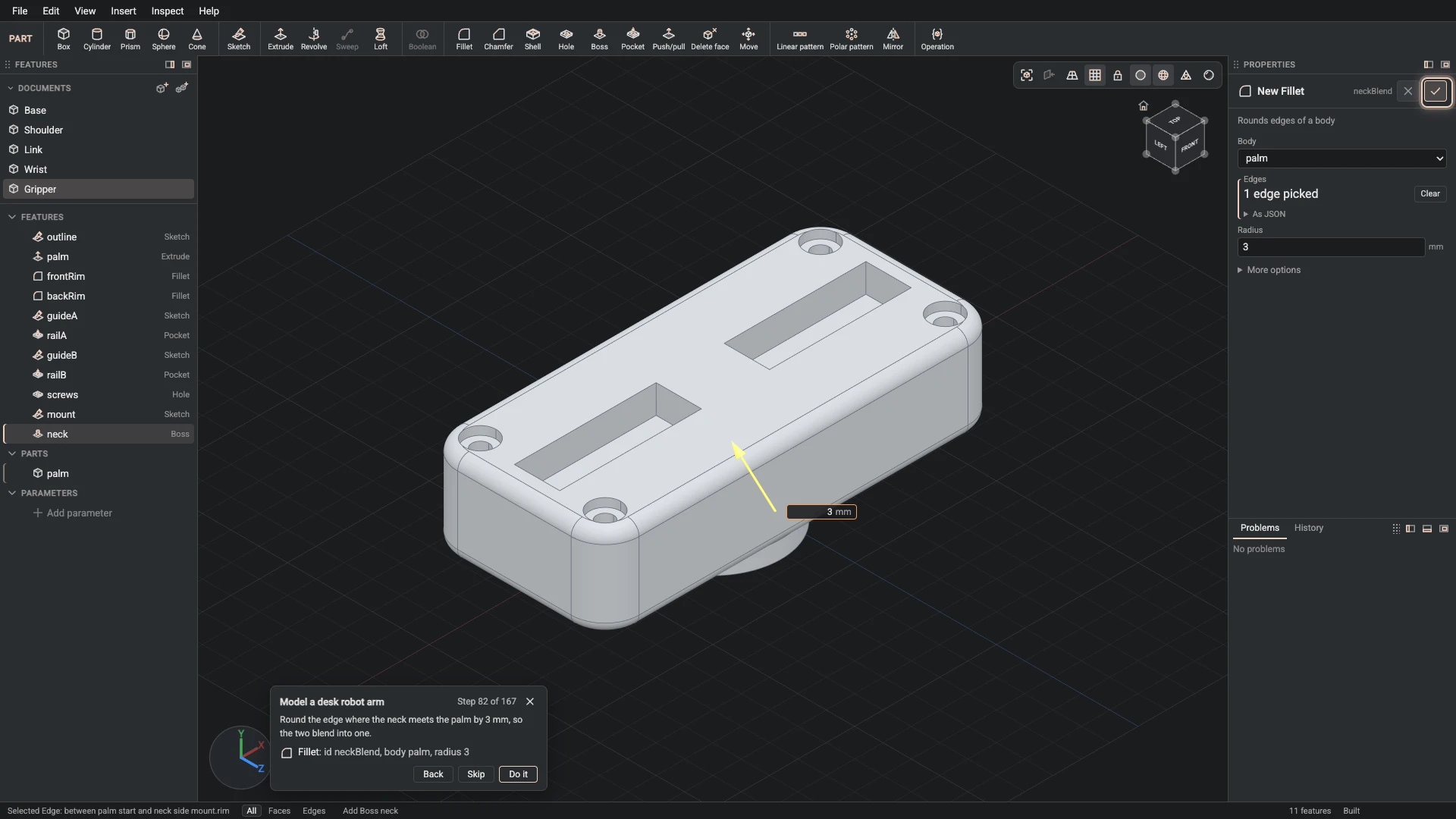
Fillet, from Insert > Fillet: id neckBlend, body palm, radius 3.
Round the edge where the neck meets the palm by 3 mm, so the two blend into one.
-
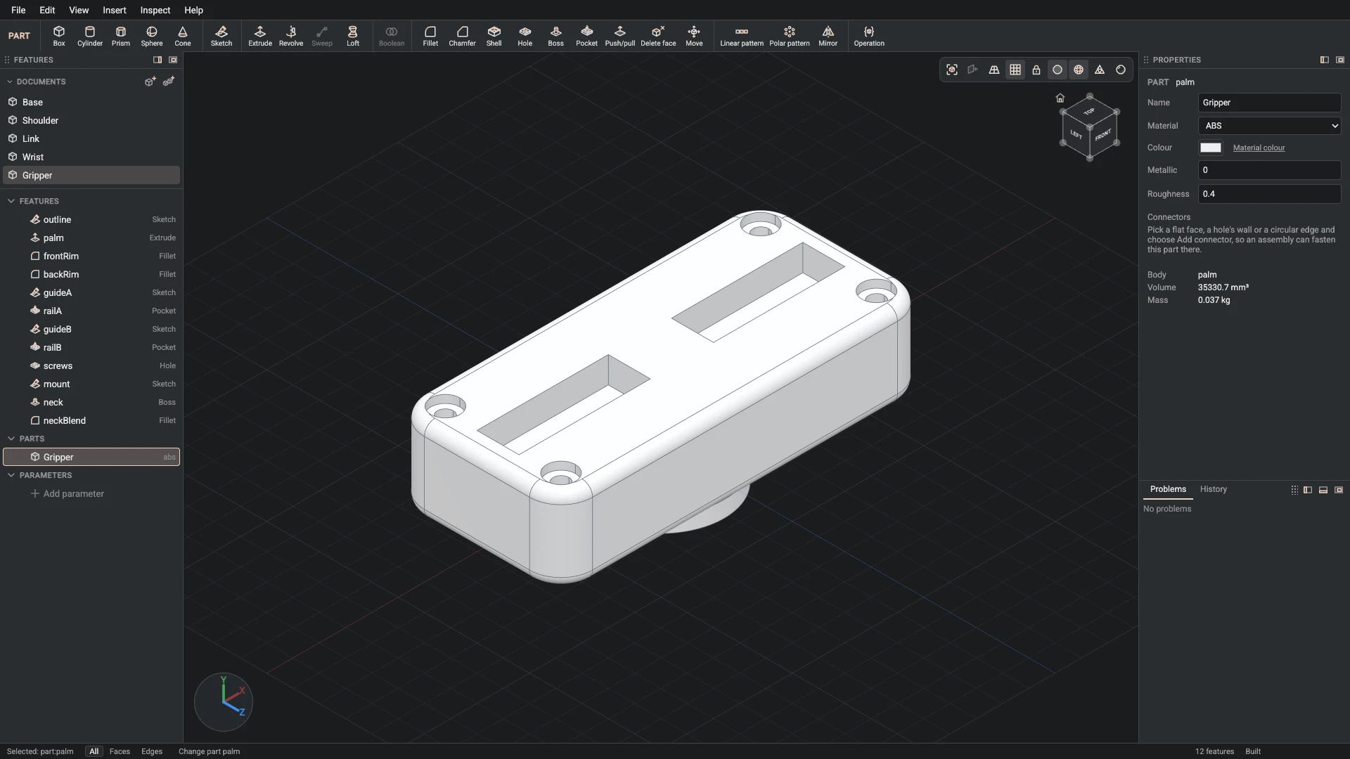
Part properties, from the Properties panel: id palm, name Gripper, material abs, color #eceef1, metallic 0, roughness 0.4.
Name the part Gripper: white ABS, like the shoulder.
-
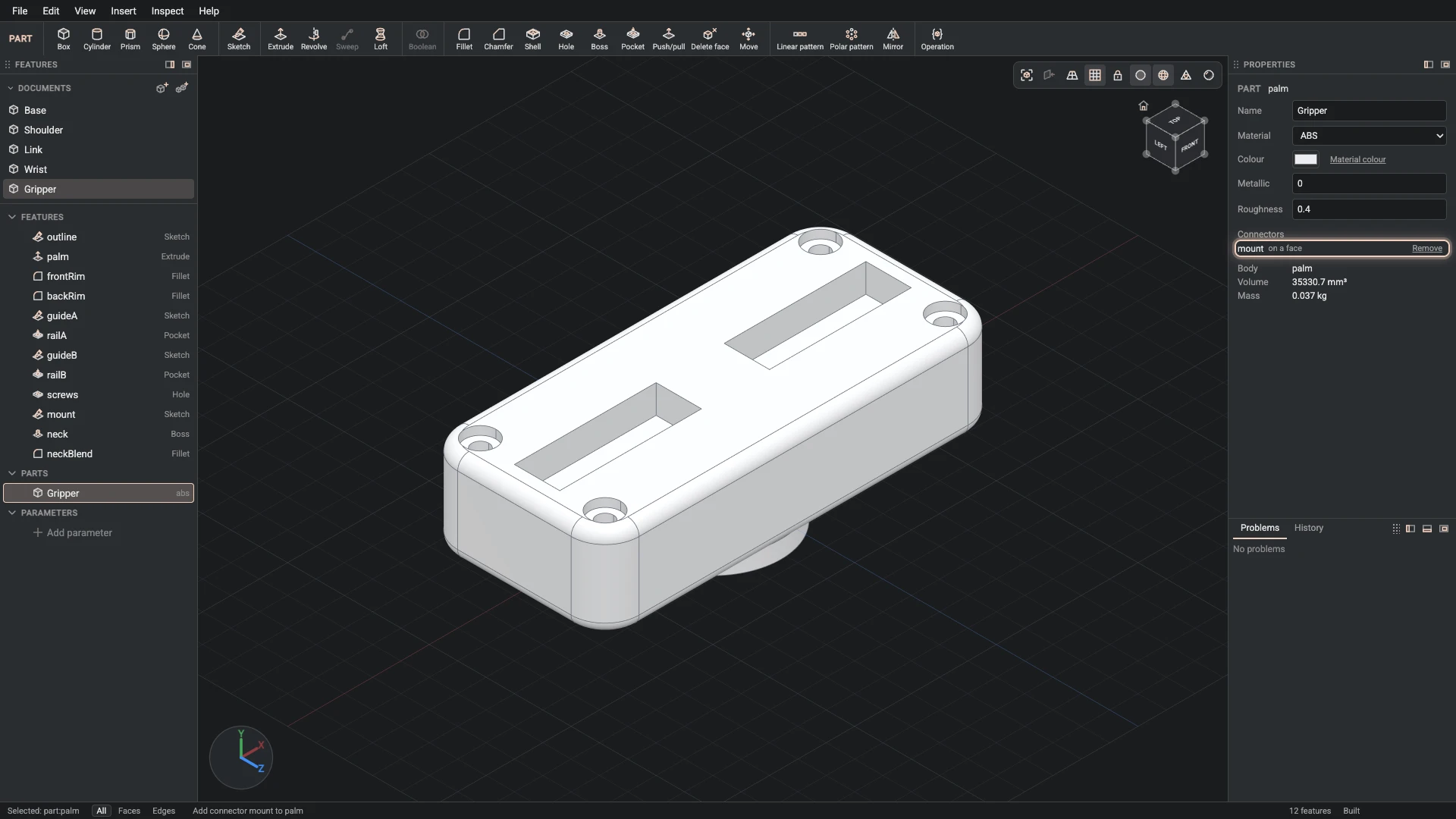
Add connector, from Insert > Add connector: part palm, id mount, on the end face of neck.
Add a connector on the neck's end. The gripper is fastened to the wrist's flange there.
-
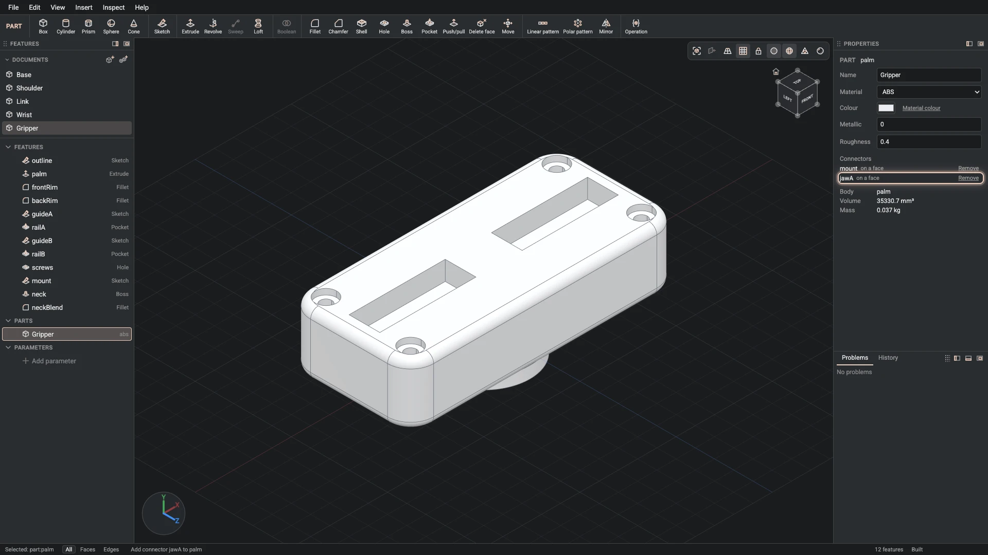
Add connector, from Insert > Add connector: part palm, id jawA, on the side face of railA, origin -6, 13.5, 0.
Add a connector at the end of the first rail, where the first jaw's carriage slides.
-
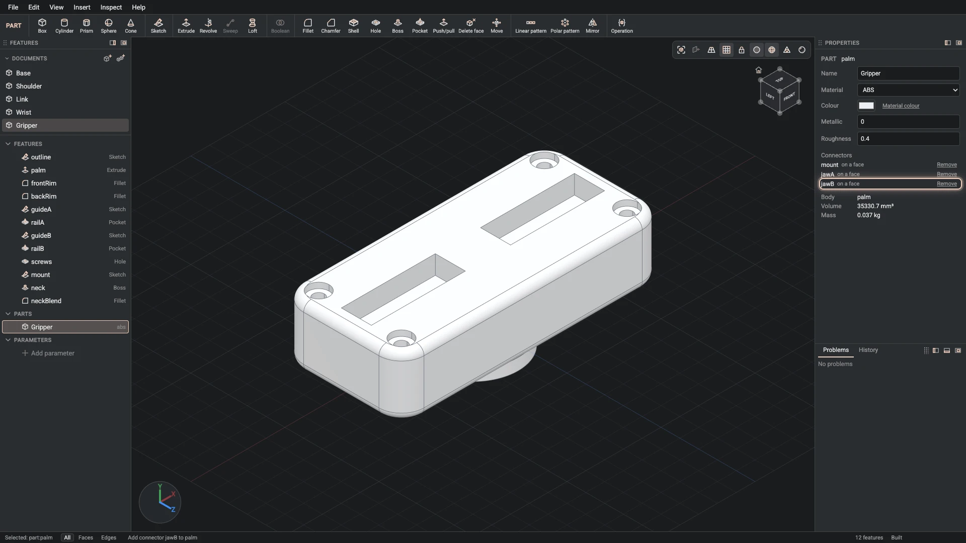
Add connector, from Insert > Add connector: part palm, id jawB, on the side face of railB, origin 6, 13.5, 0.
Add a connector in the second rail for the second jaw, facing the other way.
-
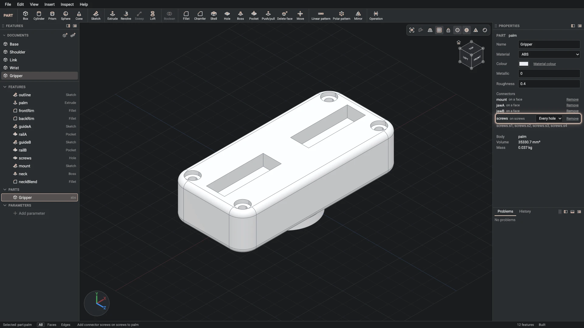
Add connector, from Insert > Add connector: part palm, id screws, on the end face of palm, axis the wall face of screws.
Add a connector on the top face, its axis along the screw holes, for the cover screws.
Verified against the product in October 2026