Sketches
A sketch is a flat outline that other features use: an extrude or a revolve takes a closed outline, a sweep travels along an open one, and a boss or a pocket raises or sinks one drawn on a face of the part. How the Designer works shows where sketches fit among the features.
Start a sketch
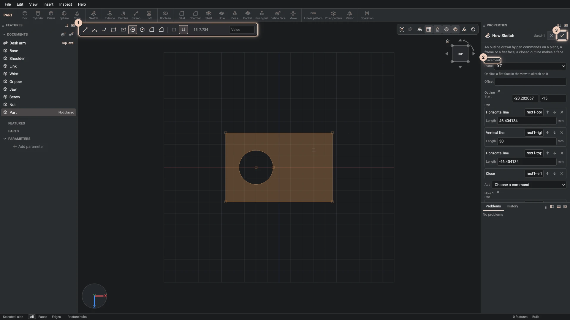
- In a part document, choose Insert > Sketch, or Sketch on the toolbar. An empty part offers it in the middle of the view too.
- Its dialog opens in Properties. Under Placement, choose the Plane, XY, XZ or YZ, and an Offset along it if you like. With Y up, XZ is the ground. To sketch on a flat face of the part instead, click that face in the view.
- The view turns to look straight at the sketch, and the sketch bar appears along its top.
Draw with the sketch bar
Pick a tool, then click in the view. Each tool has a key as well:
| Tool | Key | What it draws |
|---|---|---|
| Line | L | straight segments, point by point; click the start again to close the outline |
| Arc | A | an arc on from the last point: click where it ends, then a point it passes through |
| Tangent arc | T | an arc that leaves the last segment smoothly: click where it ends |
| Rectangle | R | a rectangle from two opposite corners |
| Centre rectangle | a rectangle from its centre and a corner | |
| Circle | C | a circle from its centre and a point on it |
| Polygon | P | a regular polygon from its centre and a corner |
- Typed sizes. While a tool waits for a size, type it, such as a circle's radius, and Enter uses it.
- Round corner and Bevel corner round or bevel a corner where two lines or arcs meet: click the corner. Type a radius or a distance to change the corners you just made.
- Close outline draws a straight segment back to where the outline started.
- Snap pulls the pointer to the sketch's points, to lines level or upright with them, and to the grid.
- Enter finishes the outline and leaves it open. Esc drops the point just placed, then stops the outline, then puts the tool down.
OK adds the sketch to the part's features, ready for a feature such as Extrude to use.
Every point is a pen command
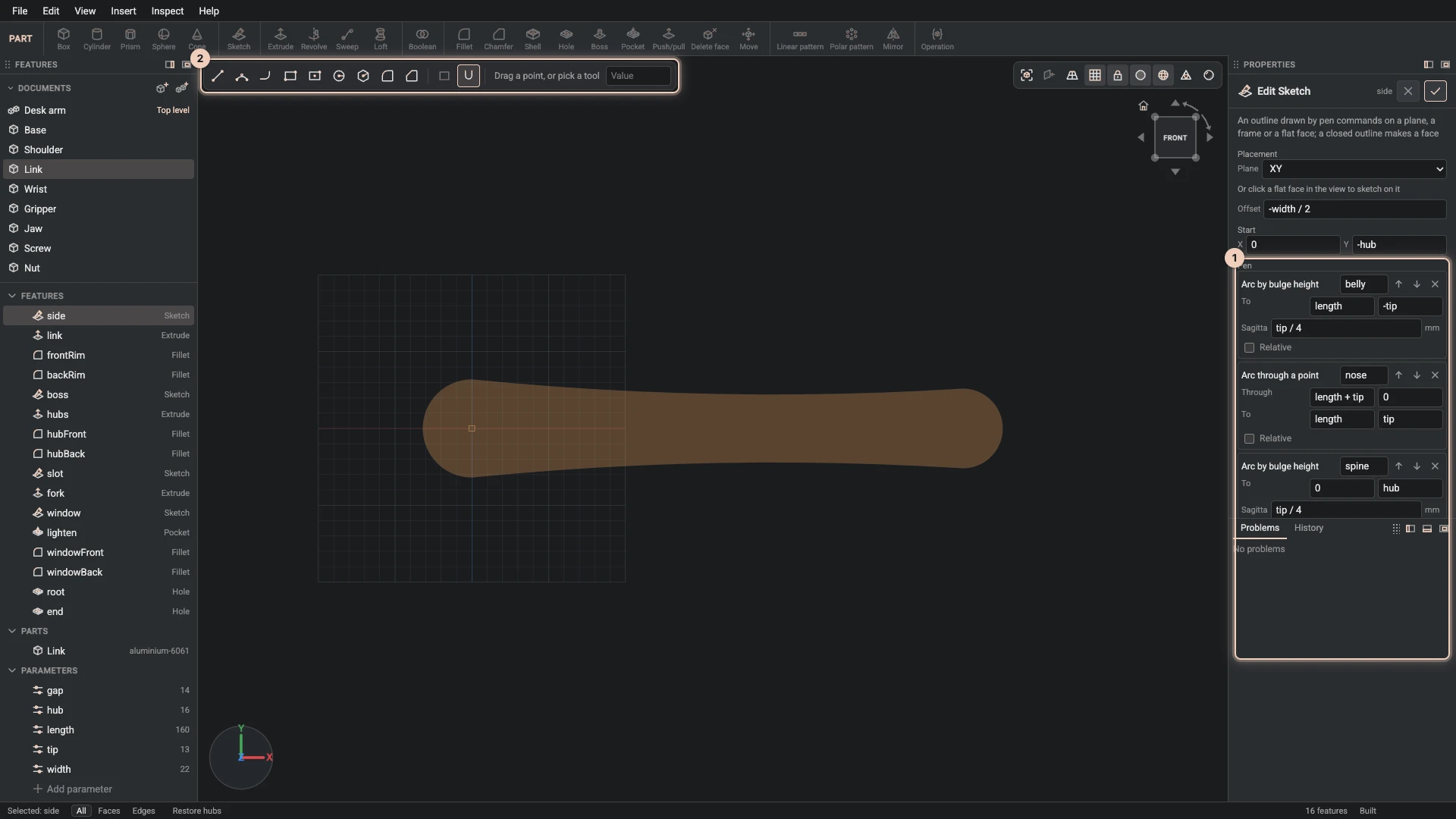
What you draw is kept as a list of pen commands, which the dialog shows under Pen: where the pen starts, then each line and arc and where it goes. Right-click a sketch and choose Edit feature to change any of them; while you do, the view shows the part only as far as the sketch. The picture shows the side outline of the desk arm's link, from the showcases.
- Numbers can be expressions. Every number may be written in the part's parameters, such as
length + tiportip / 4, so the outline follows when a parameter changes. Parameters explains them. - Relative or absolute. A point is measured from the one before it while Relative is ticked, or from the sketch's origin when it is not.
- Commands have ids. A feature made from the sketch names its side faces after the pen commands' ids. A fillet can then name "the side made by the belly arc", and finds it again after the outline changes. References explains why that matters.
Closed outlines, holes and paths
- A closed outline makes a face, which an extrude, a revolve or a loft uses.
- An open outline is a path for a sweep. To keep a closed outline as a path, such as a ring to sweep along, untick Face under More options.
- Holes. Draw a closed outline inside another, such as a circle inside a rectangle, and the sketch keeps them as Loops: the first is the outside, each further one a hole in the face. The picture at the top shows one.
Verified against the product in October 2026