Introducing the Designer: Parametric CAD by Clicking, Built for People and Agents

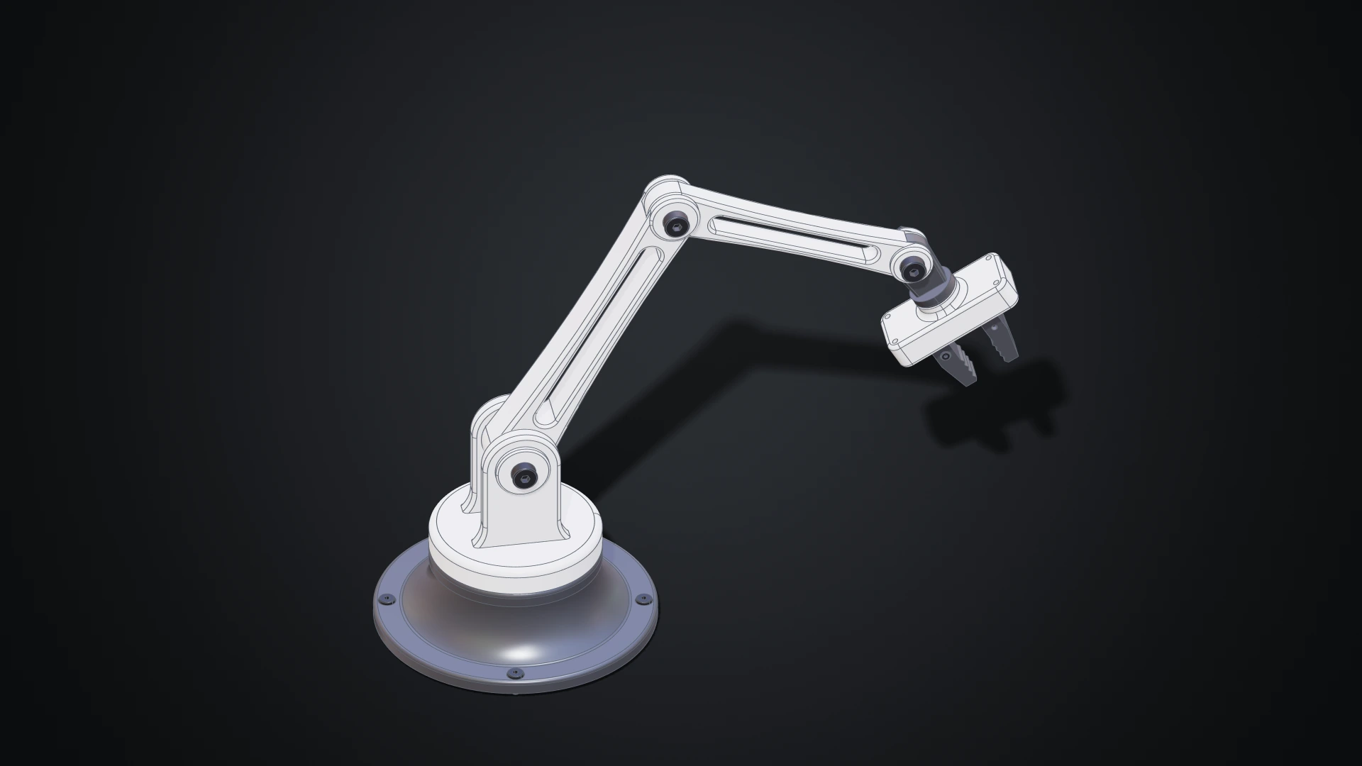
Until now, making geometry on Bitbybit meant writing it: wiring nodes in Rete, snapping blocks in Blockly or typing TypeScript. Those editors shine when a model is a program, a family of parts generated from a few numbers. But a lot of design isn't programming. You want to draw a profile, pull it into a solid, round an edge, drill four holes and see the result straight away.
The Designer is our answer: a parametric CAD modeller you use with the mouse, in your browser. Draw a sketch, extrude it, fillet it, drill it, then put parts together with joints and pose the assembly. Every step is kept, so changing a size later rebuilds everything that depends on it. The Bitbybit OCCT Kernel does the modelling on your own machine, so there is nothing to install. And because the Designer was built for AI agents as much as for people, an agent can work in the same document beside you, while you keep or undo each of its changes.
Watch a desk arm built from a blank page
The film follows a desk robot arm from its first sketch to a moving assembly: a profile drawn and revolved into the base, a shoulder extruded, rounded and mirrored, a link driven by five parameters, the parts joined, posed and cut open, and finally a change made by a browser agent and kept in review. Every build runs at its real speed and the time it took is on screen; the stretches that are sped up are marked as a time-lapse.
A CAD program in a browser tab
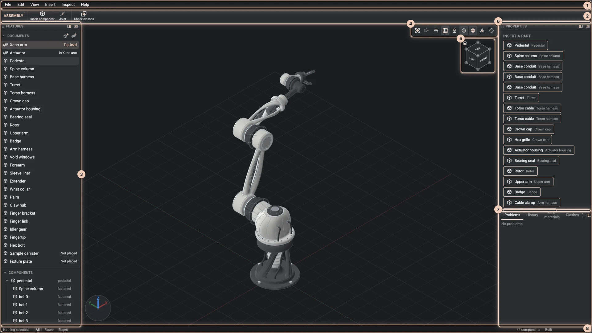
The Designer looks and works like a desktop CAD program. Menus and a toolbar run along the top. The Features panel on the left lists the project's documents and the history of the one you have open. The view sits in the middle, with a view cube and a bar of display switches, and Properties and the dock fill the right. Each panel docks left, right or at the bottom, or floats. Press Ctrl+K (⌘K on macOS) to find any command by name.
A Designer project lives on bitbybit.dev like any other: it saves as you work and keeps versions you can go back to. The geometry a build makes is kept beside the project, so even a large model usually opens in seconds.
Sketch, then build features on it
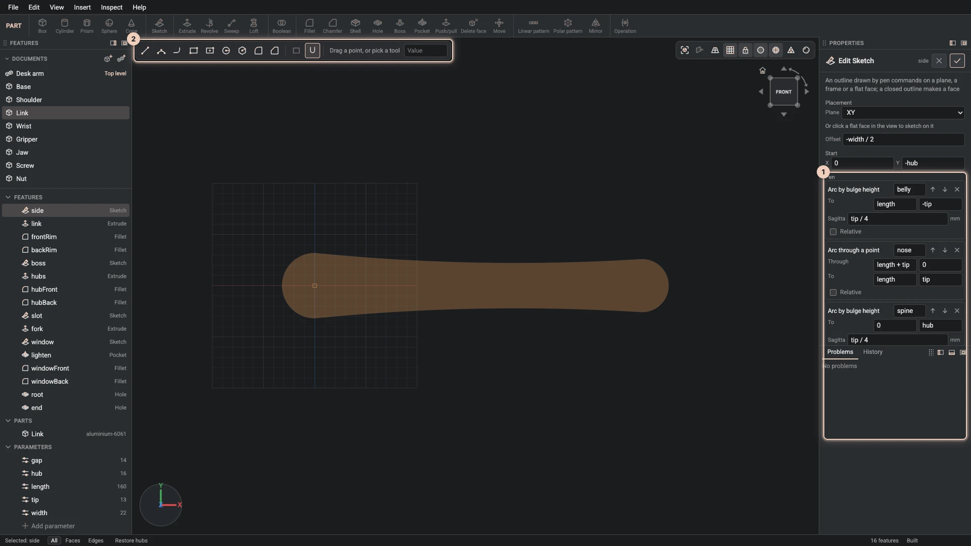
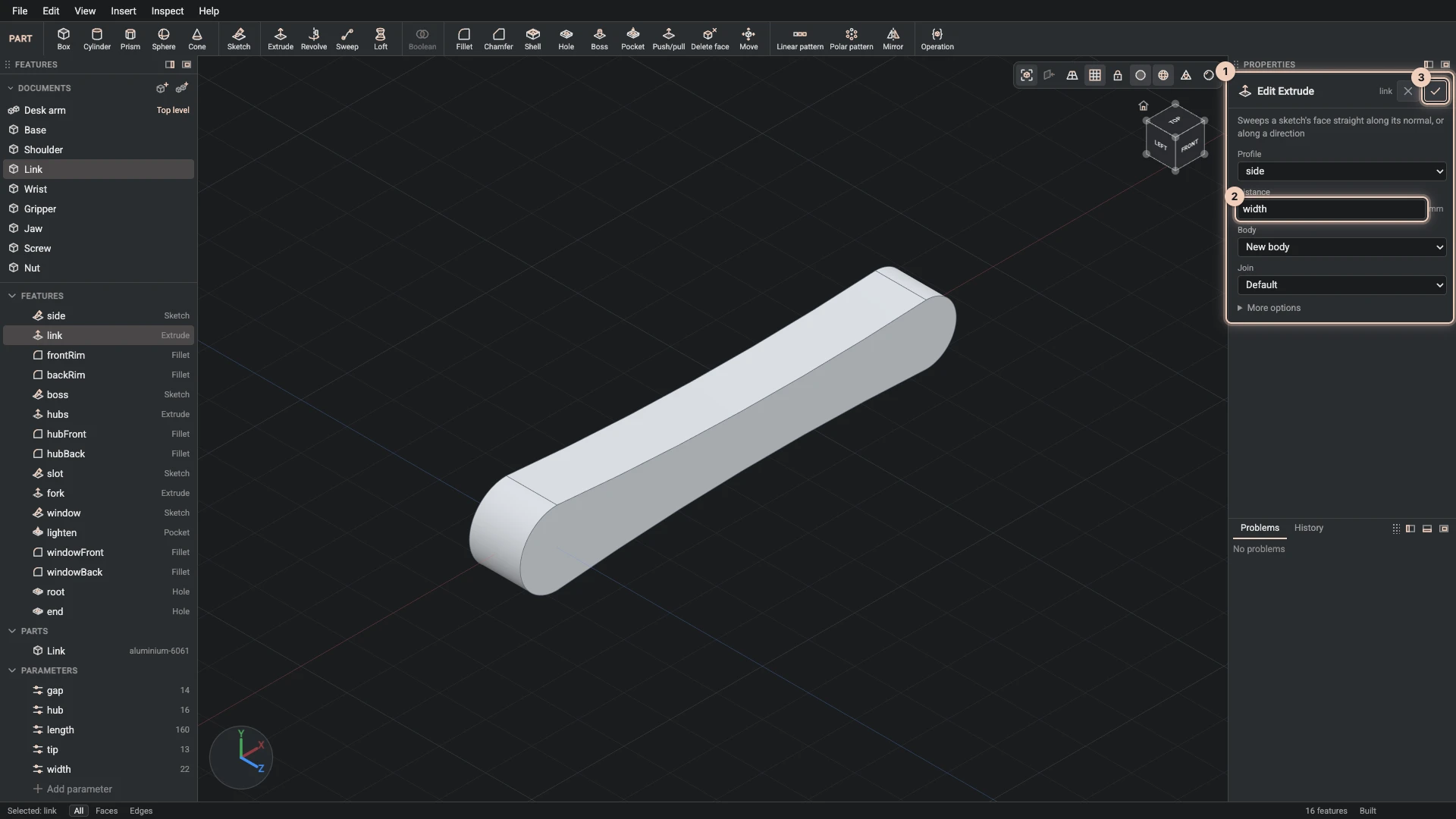
A part starts with a sketch: lines, arcs and rounded corners drawn on a plane or on a face of the part, with snapping, a grid and typed values. Every segment has a name, so the features that follow refer to the faces it makes by name rather than by a fragile number.
From a sketch you build features: extrude and revolve, loft and sweep, a boss or a pocket on a face, push/pull of any face, fillets and chamfers, a shell, holes with counterbores, linear and polar patterns, mirror, booleans and move. When those are not enough, an operation feature runs a modelling operation of the Bitbybit API as a step of the history.
Each feature opens a dialog with a live preview and handles in the view. Drag a handle and a light proxy follows the pointer at once, while the kernel builds the real preview behind it.
Every step is kept
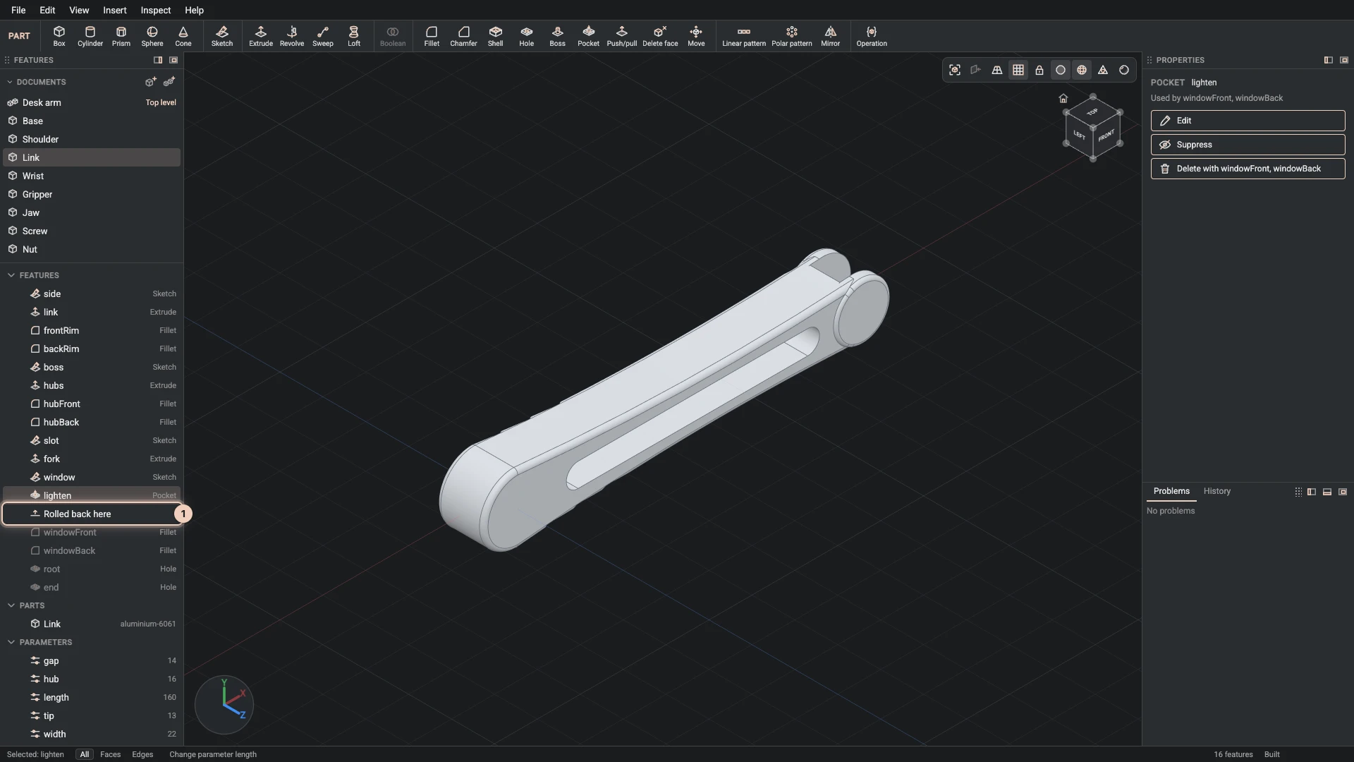
The Features panel is the part's history. Double-click any feature to edit it in its dialog, drag it to a new place in the order, or roll the part back to see it as it was at any step. References follow faces by the names the document gives them, so an edit early in the history doesn't quietly break a fillet that comes later. When a reference does get lost, the feature turns red, the Problems tab says why, and a repair view offers the faces that fit.
Parameters drive the design
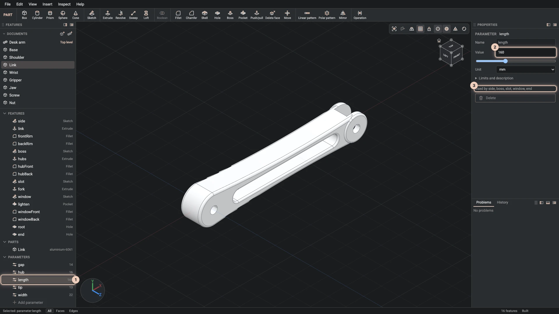
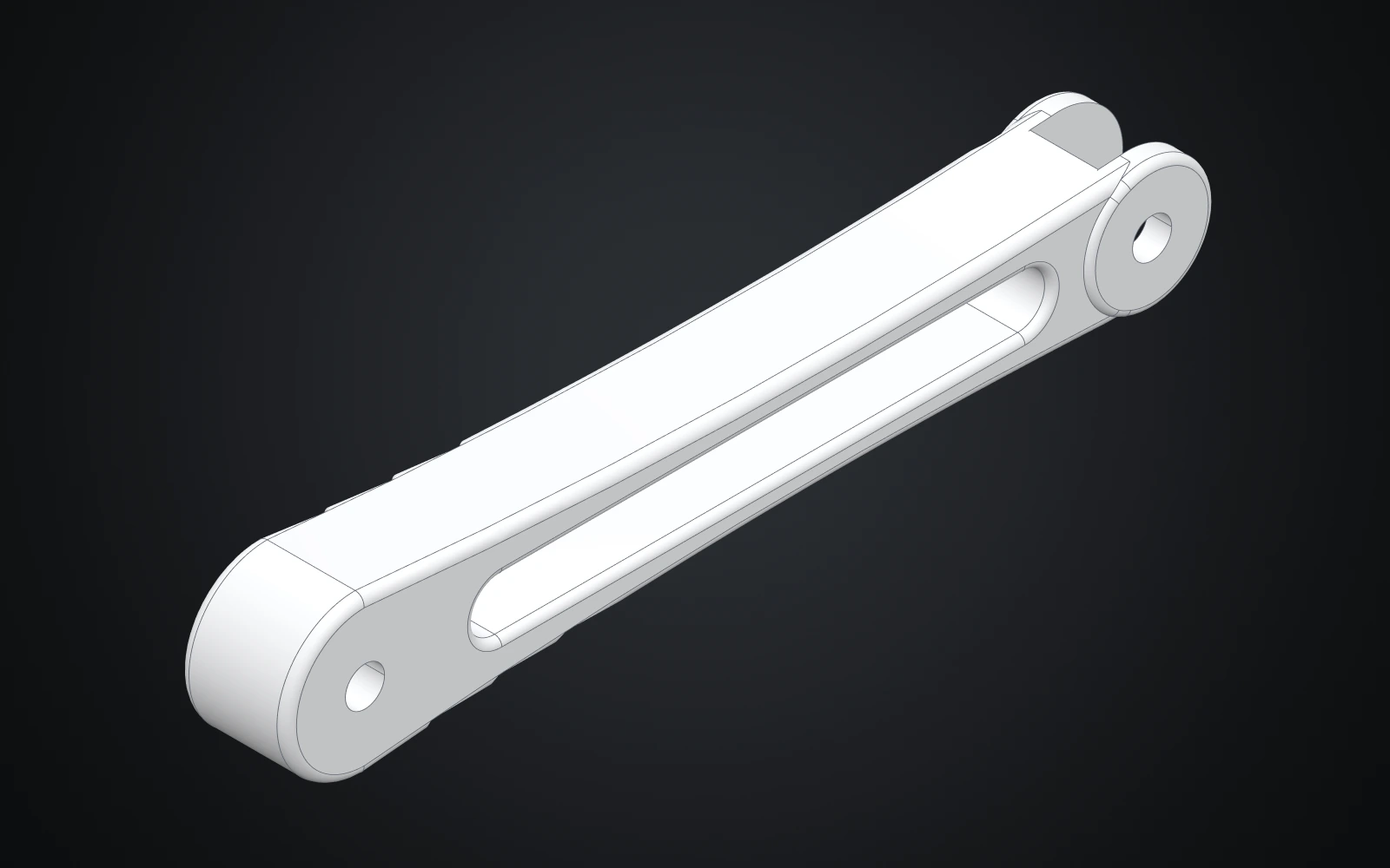
Name the sizes that matter and write the others as expressions of them. The desk arm's link is one document with five parameters (length, width, gap, hub and tip), and its waisted outline, the fork at its far end, the lightening window and both pivot holes are all expressions of them. Change the length and the whole link follows.
A configuration keeps a set of values under a name, so one model can have a Rest and a Reach pose, or a short and a long version. And one document can serve many times: the desk arm's upper arm and forearm are the same link, inserted twice with values of their own.
Parts with materials, and a realistic look
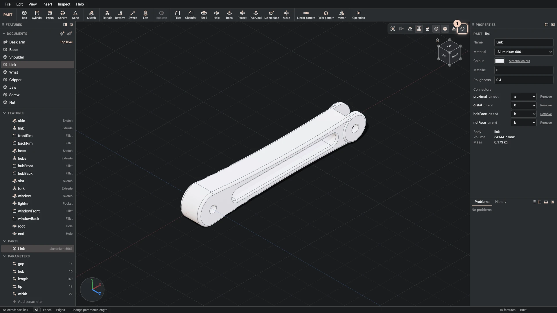
A part has a name, a material, a colour and a finish, and the Designer works out its volume and mass from the material's density. Switch on the realistic look to see the materials with reflections and soft shadows, or show only edges, or the triangles the view draws.
Assemblies that move
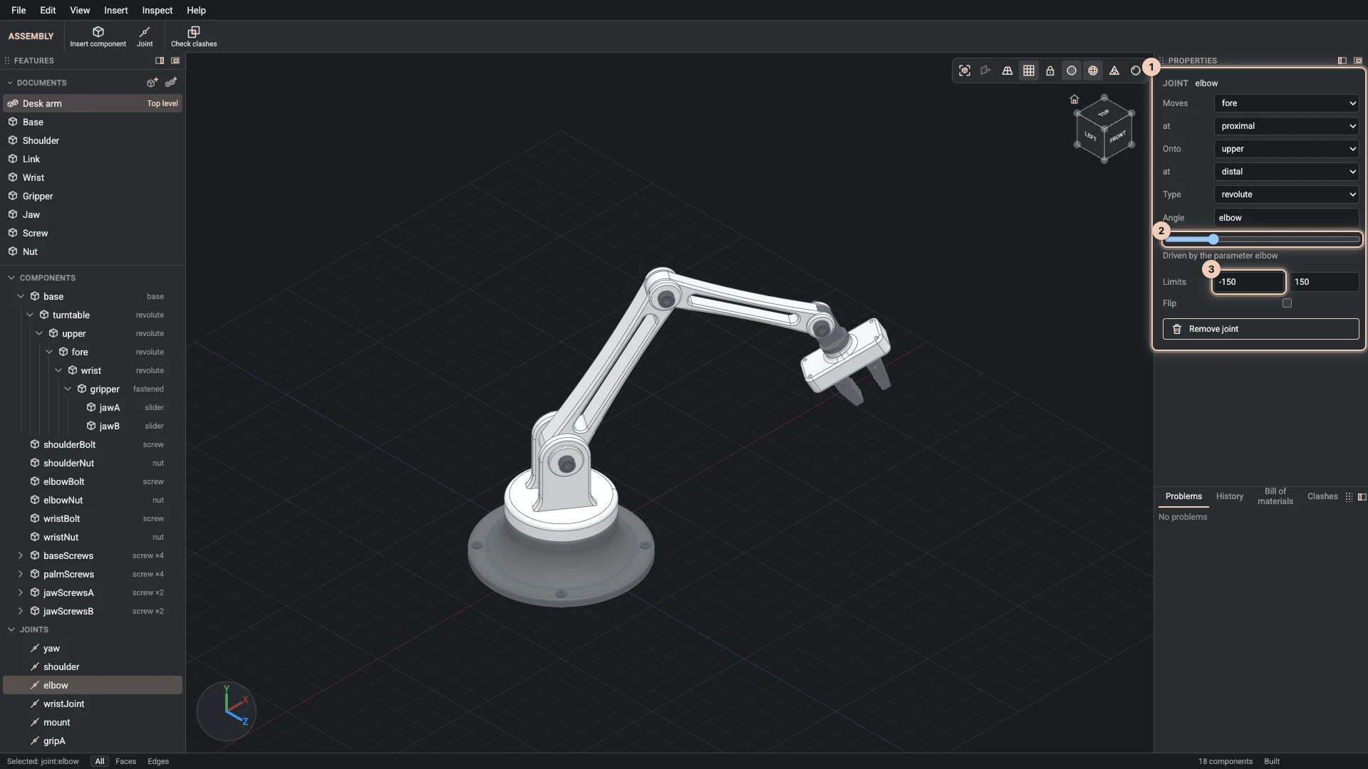
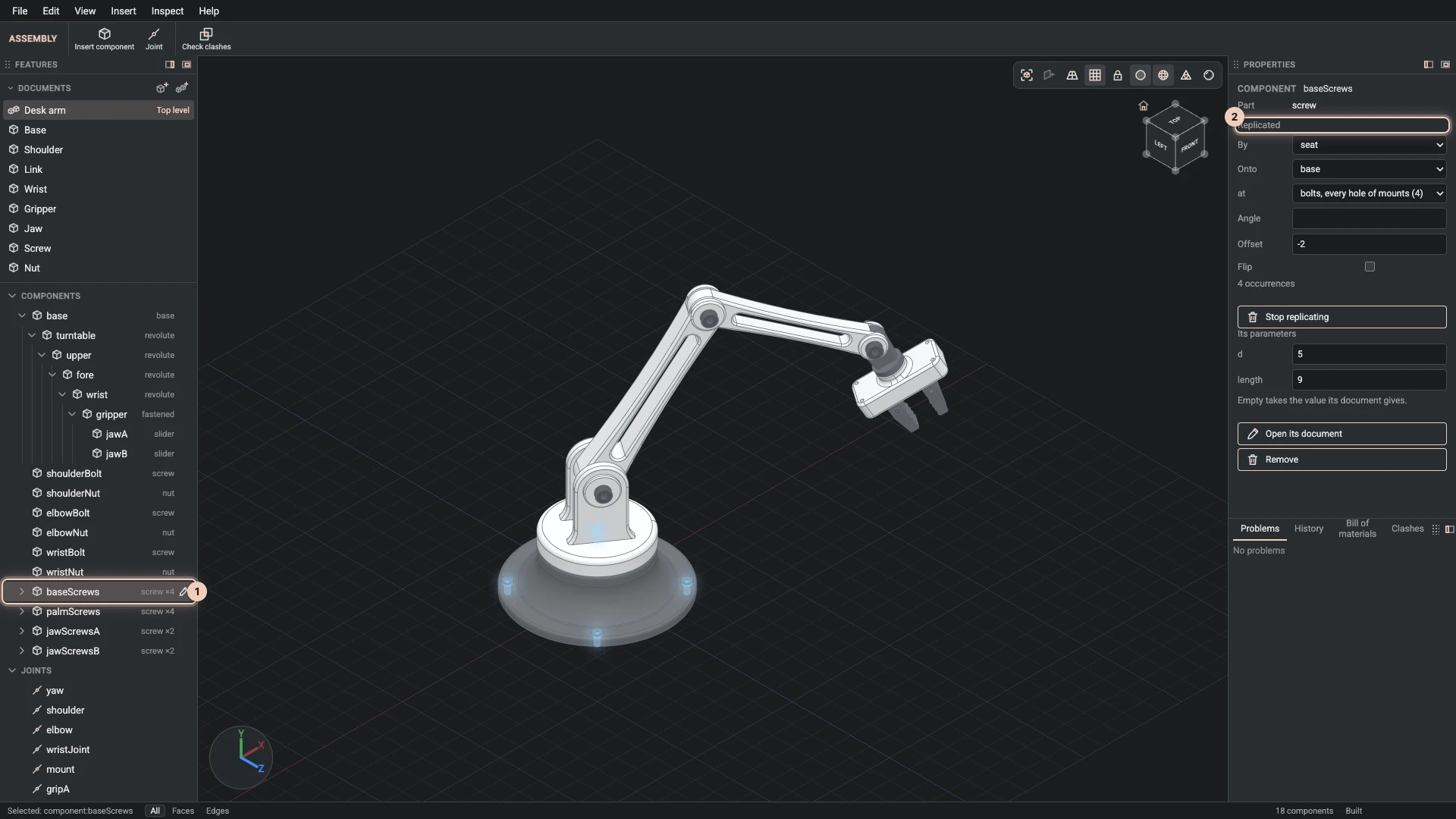
An assembly places parts as components and joins them at connectors: a flat face, a hole's wall, a cylinder or a circular edge. Joints turn or slide within limits you set, or hold a part fast, and parameters or configurations drive them. Drag a joint's value and the assembly poses straight away, while the kernel's build follows behind.
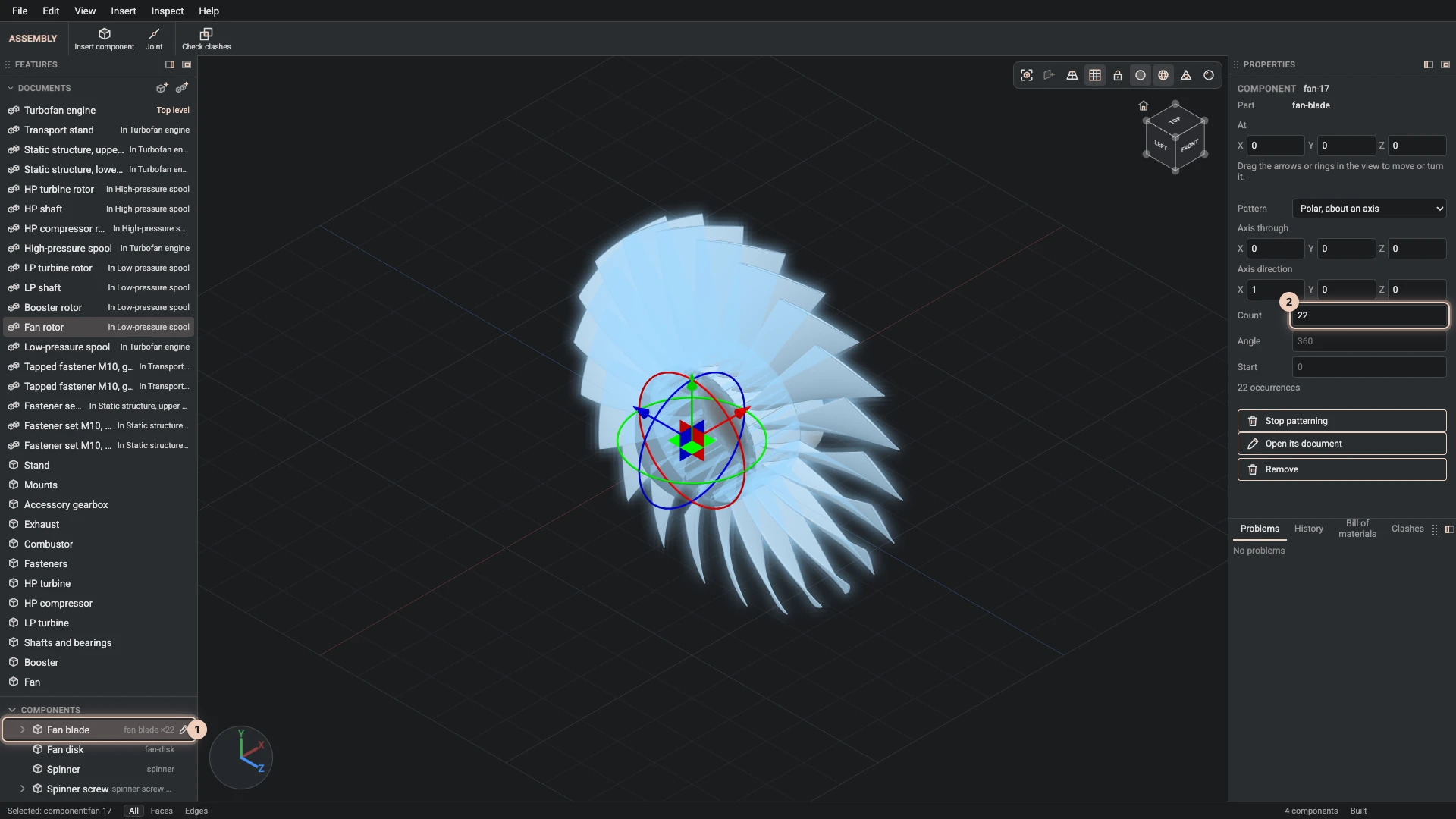
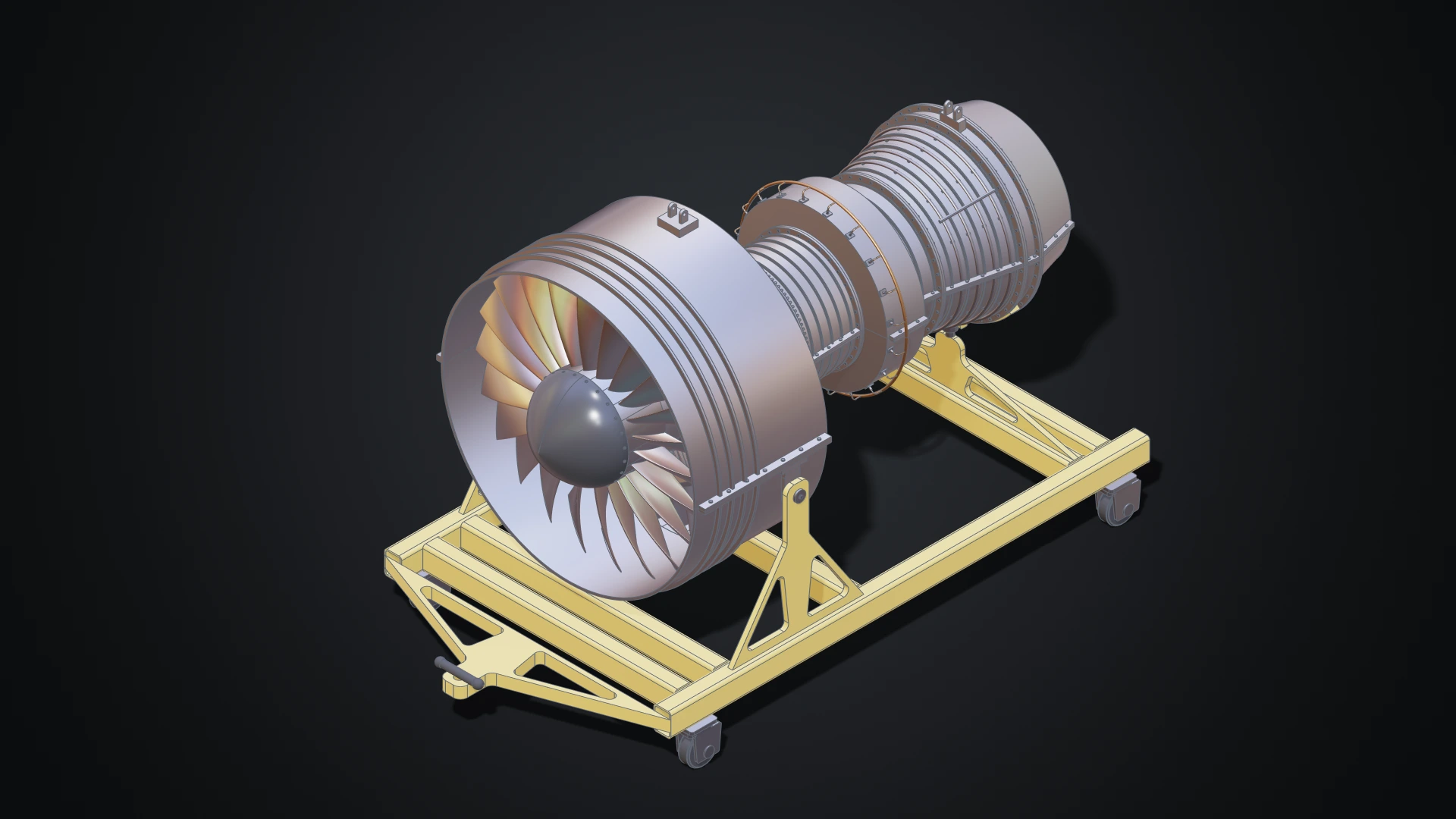
Fasteners take one step each. Replicate puts one screw on every hole of a hole pattern, and a pattern repeats a component around an axis or along a line. That is how all 22 blades of the jet engine's fan are one component.
Then inspect what you made. The bill of materials counts every part through every level. The clash check lists parts that overlap or come too close. Measure gives the lengths, areas, radii, distances and angles of what you pick. The section view cuts the model with a plane so you can look inside, with the cut filled in by the kernel.
Work beside an agent
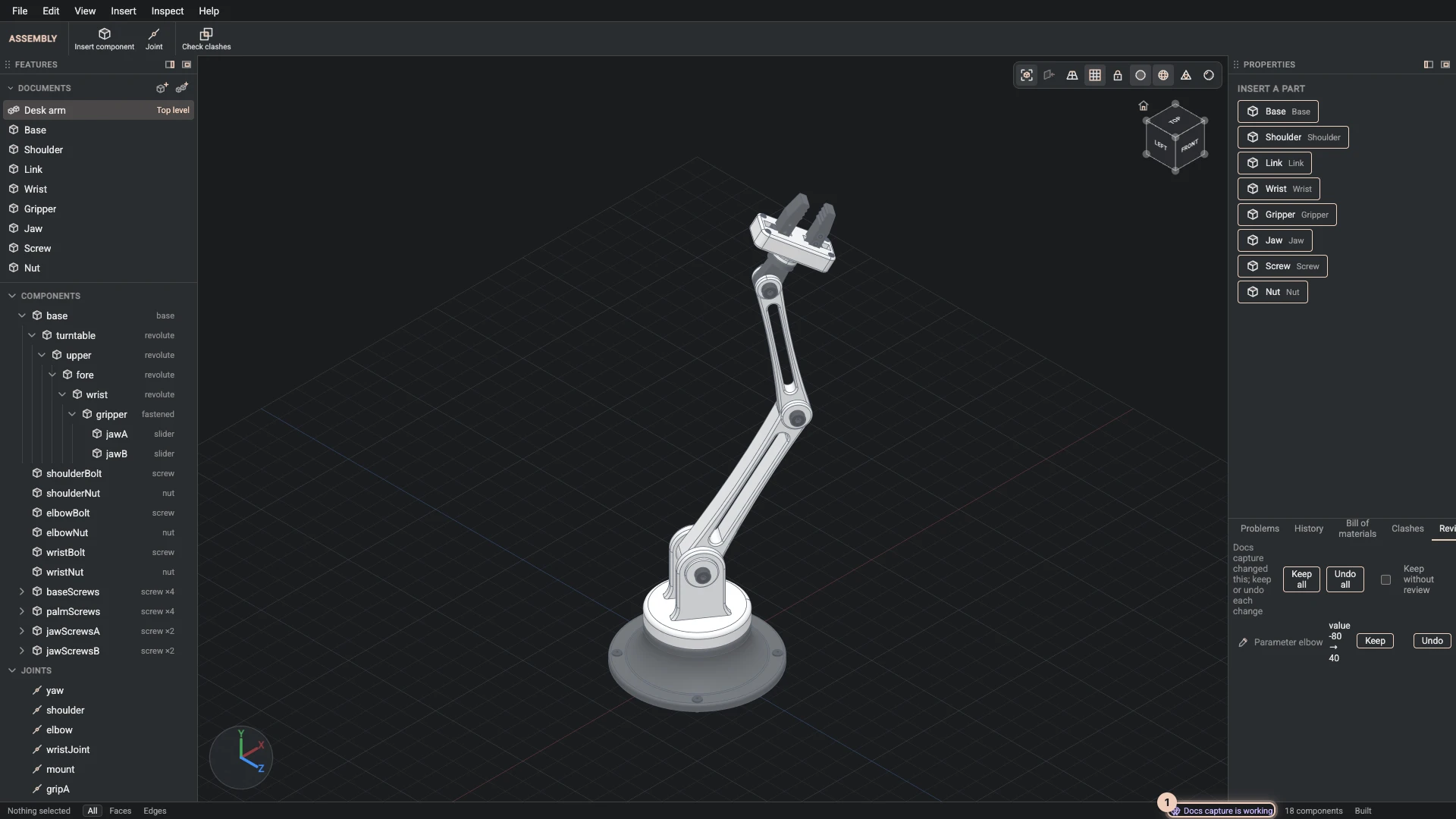
The Designer was built for two authors at once. While it is open, it offers its tools to AI agents: to the browser's own agent through WebMCP, in browsers that support it, and to scripts on the page as window.bitbybitDesigner. An agent runs the same commands you do. It can read the build, pick faces by their names, sketch, add features and joints, change parameters and capture the view. (In the film, the agent's part is a scripted run of these same WebMCP tools.)
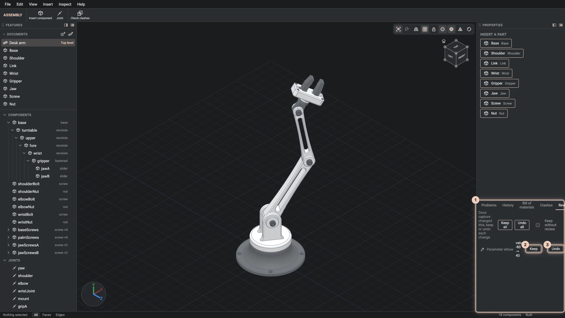
You stay in charge. The status bar names the agent that is working, its picks are drawn in a colour of their own, and every change it makes waits in the Review tab for you to keep or undo. Follow agent decides whether the agent's views move your camera. Deleting documents, imports, exports and reviewing stay with you.
Everything you do is recorded as steps, too. Save the steps gives you a file that rebuilds the project command by command. The Designer's own tutorials are written in that format, and an agent can read the steps of a session to learn how a model was made.
Learn it inside the app
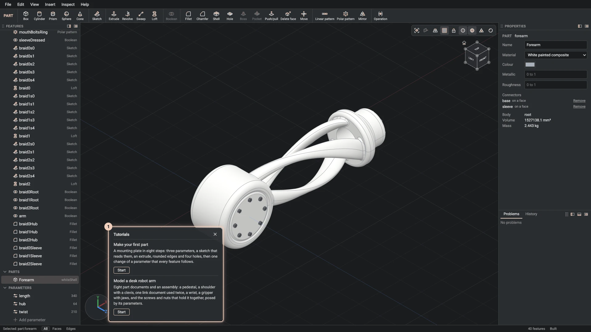
Help > Tutorials plays a tutorial right in the Designer. A card shows each step, explains it and rings the control to use. Make the step yourself, or press Do it.
- Make your first part: a plate with rounded edges and holes, driven by parameters. Start here.
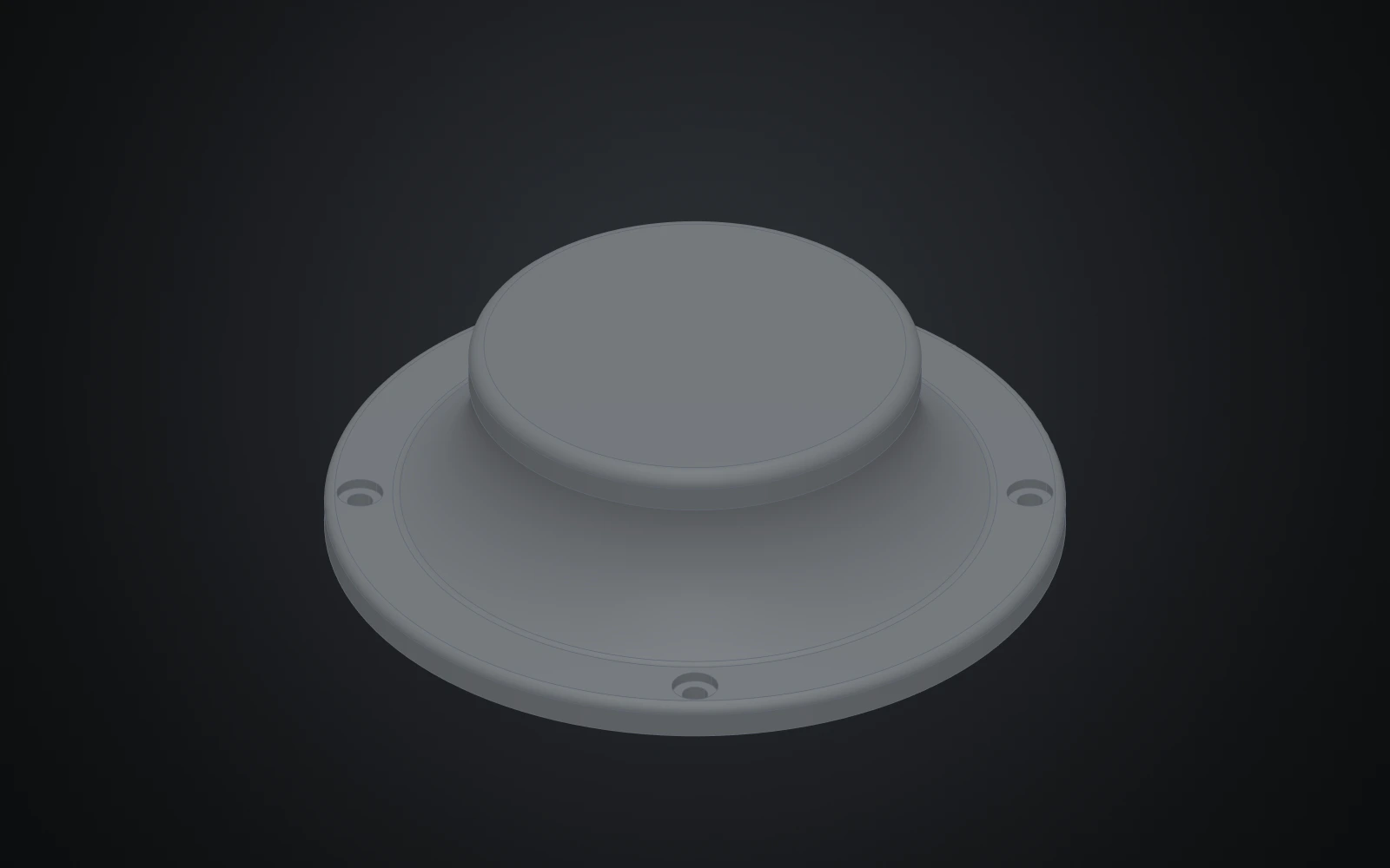
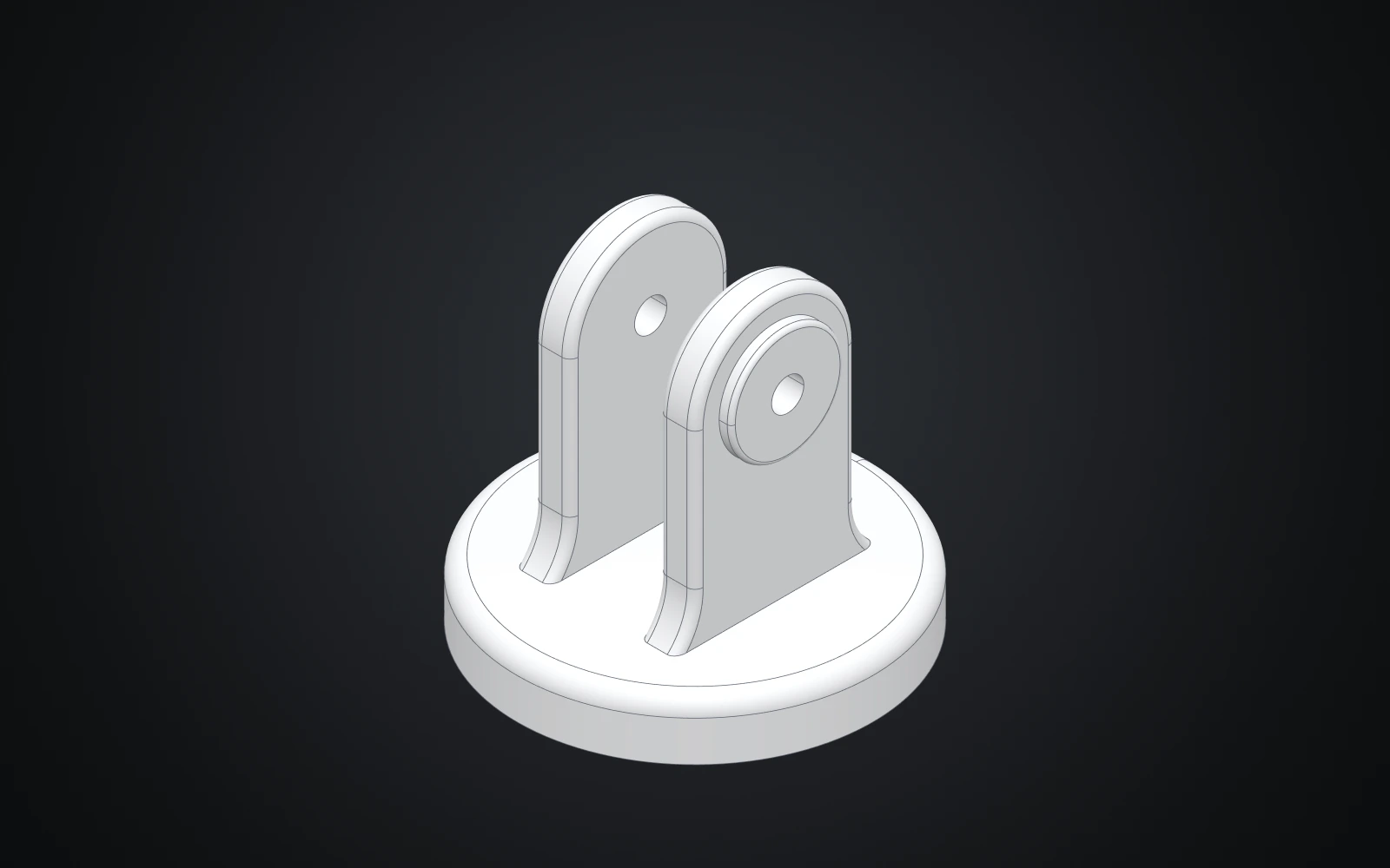
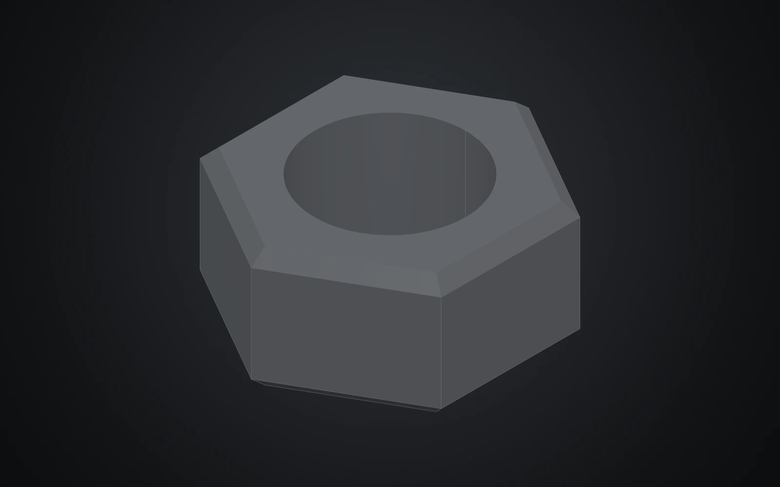
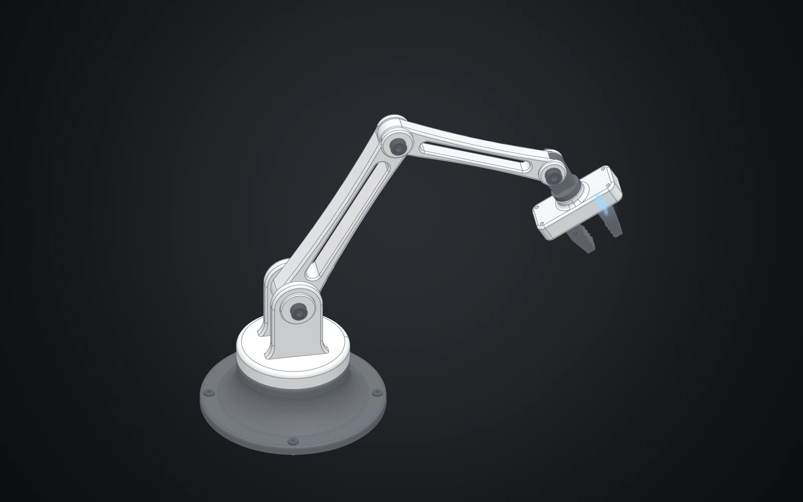
- Model a desk robot arm: nine chapters and 167 steps that make eight parts and an assembly: a revolved base, a shoulder with a clevis, one link used twice, a wrist, a gripper with sliding jaws, and the screws and nuts that hold it together. On learn.bitbybit.dev every step has its own picture.
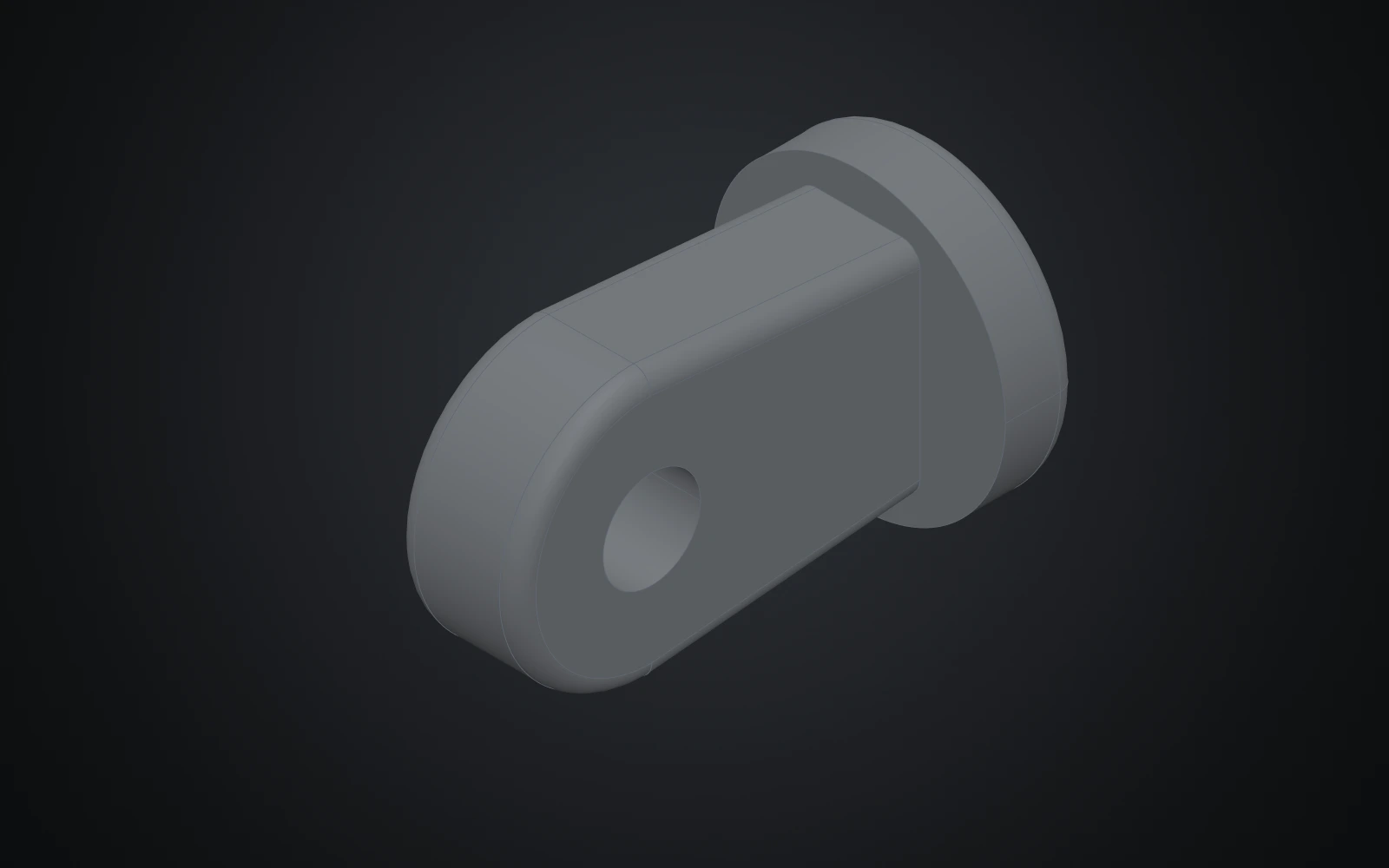
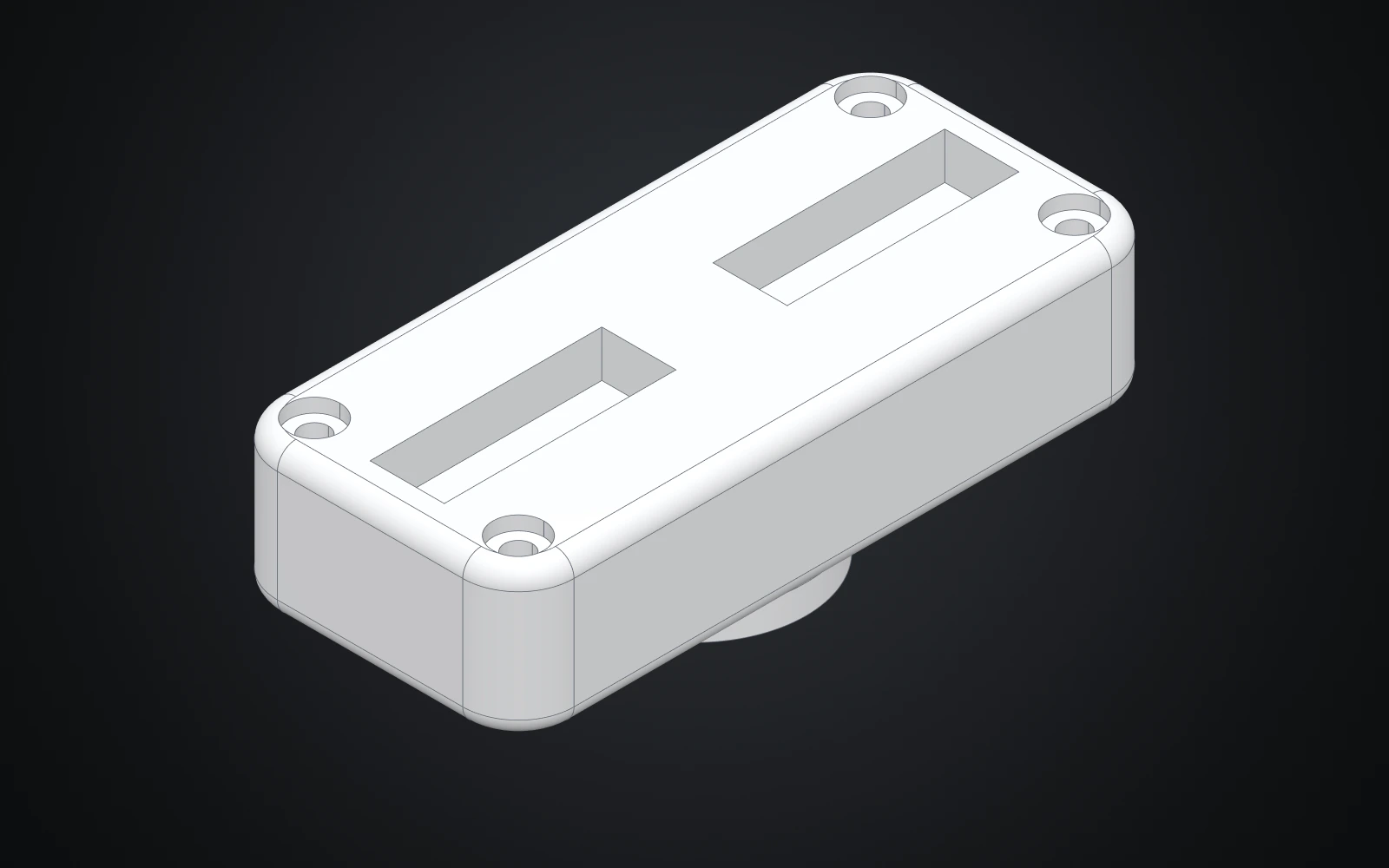
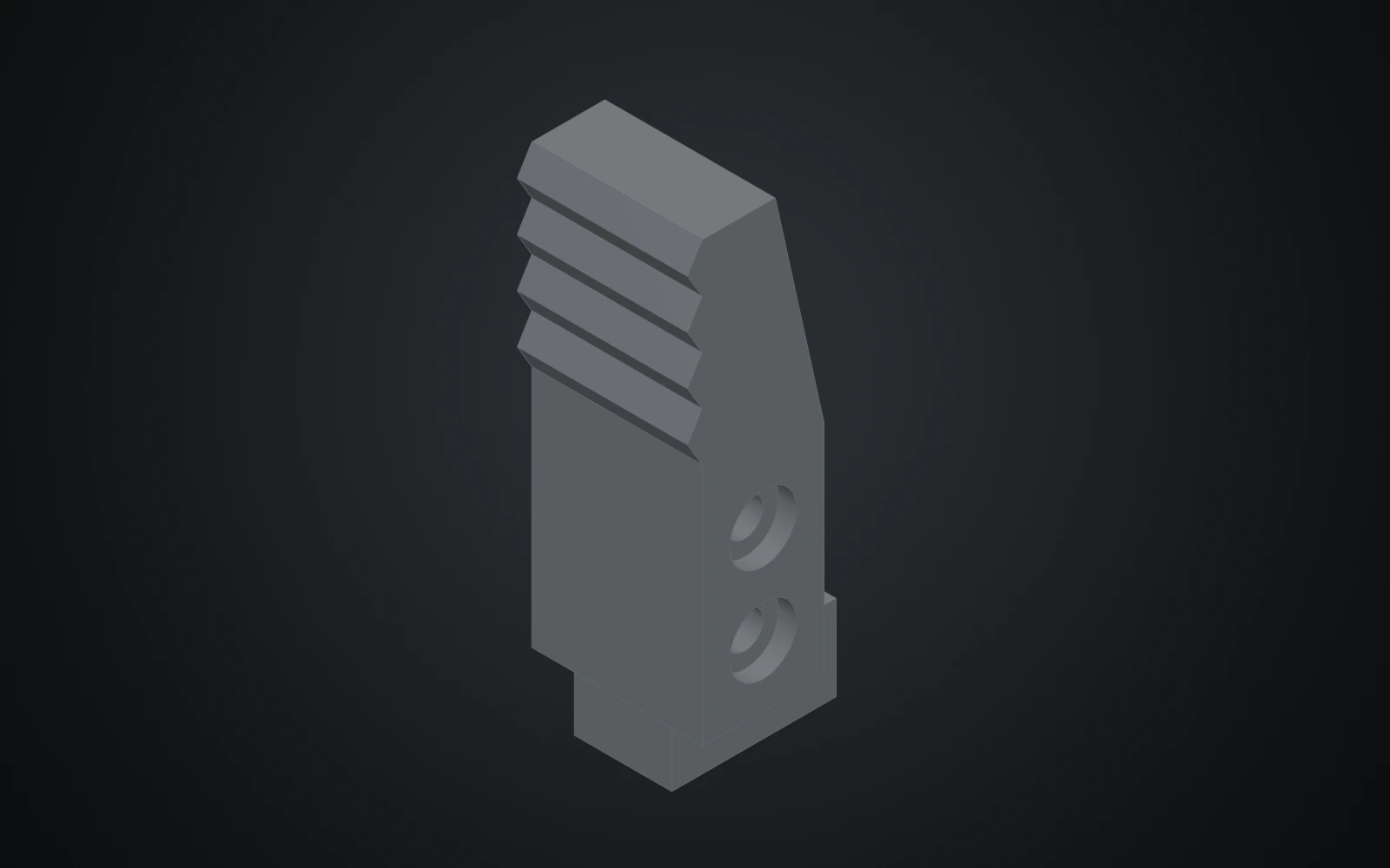
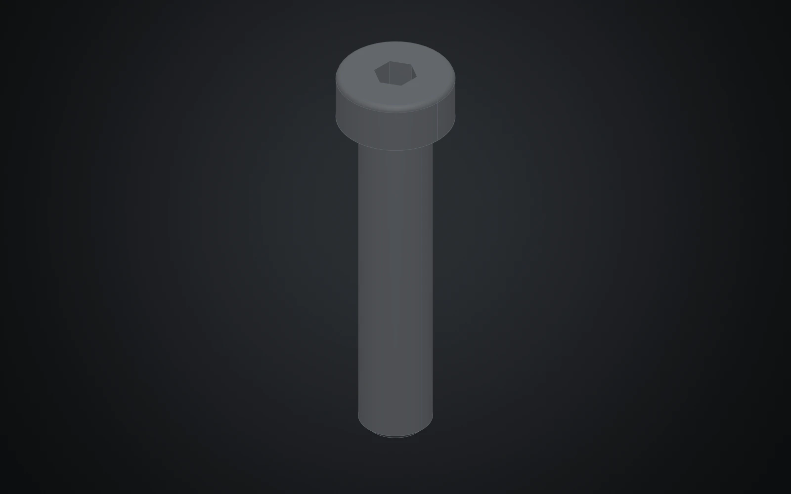
Three showcases
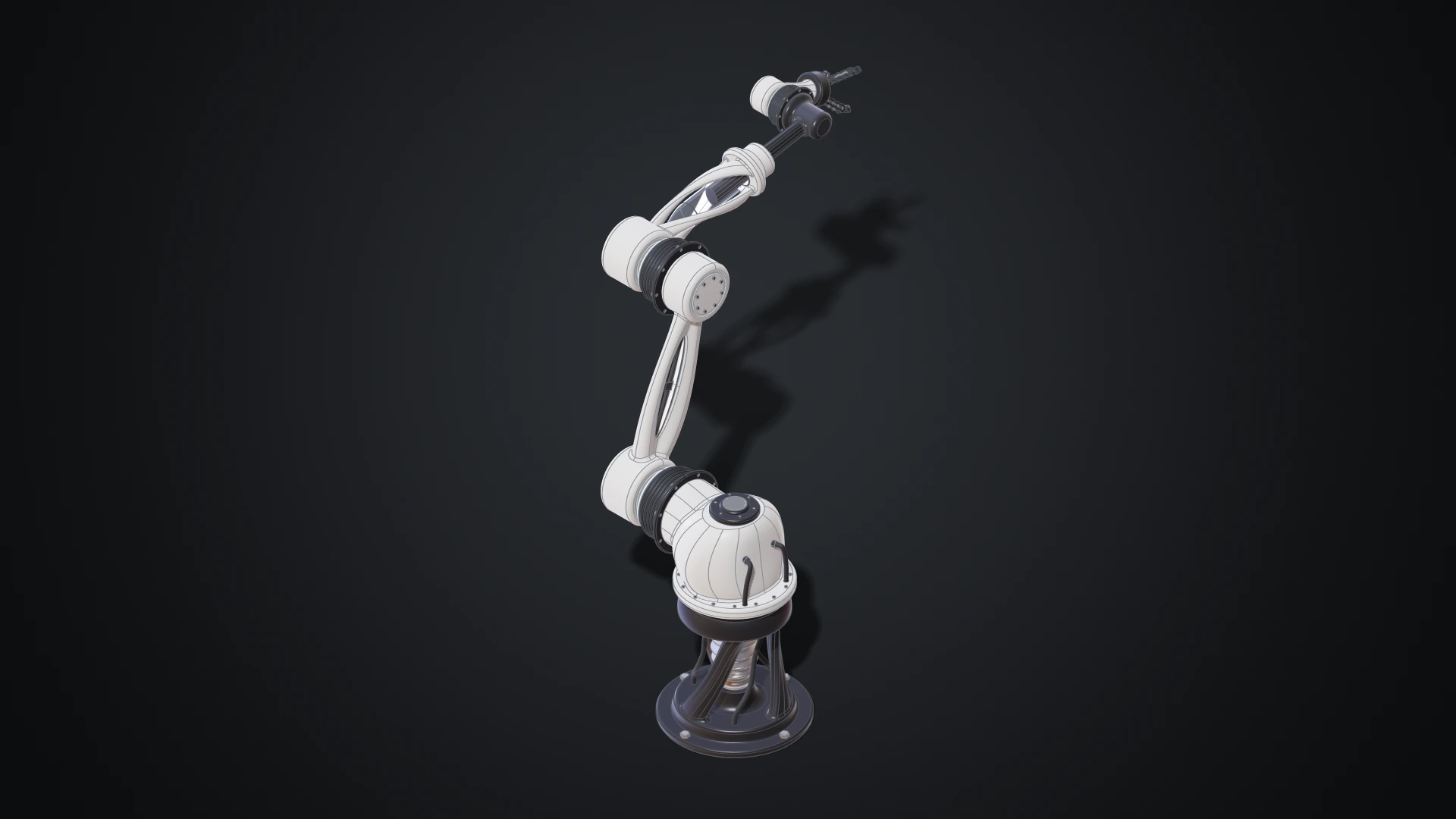
- A robot arm: a six-axis industrial arm with cable harnesses and a three-finger gripper. 28 documents and 77 components, with joints and limits at every axis and finger, posed by four configurations.
- A jet engine: a turbofan with 4,853 parts placed from 130 different ones. Each blade and vane row is one patterned component, and the engine can be shown closed, with its casing open, or exploded.
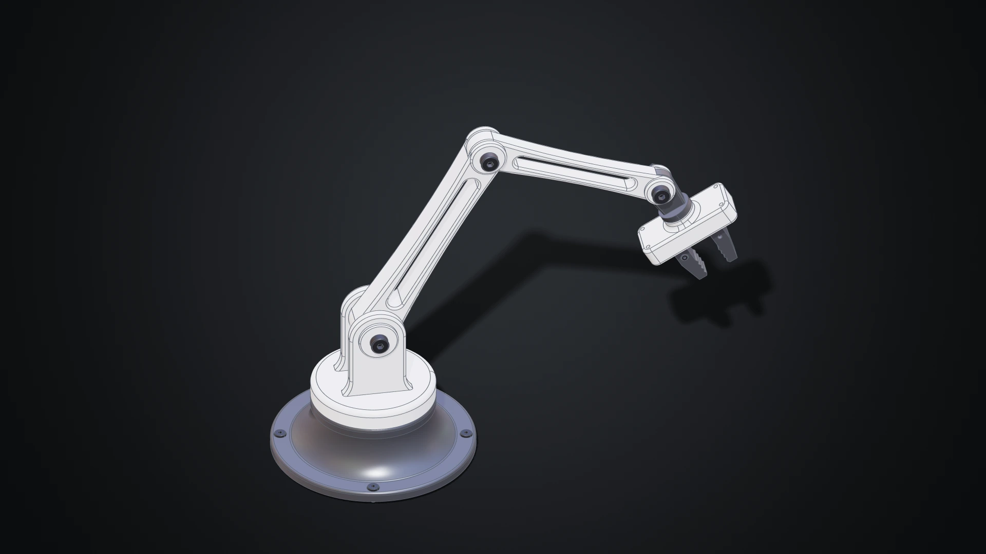
- The desk arm of the tutorial.
Open any of them in the Designer from the showcases page, or download its design documents.
Open documents, standard files
A Designer project is a set of design documents: plain JSON that describes the features, parts and assemblies. The same documents build in code with the free @bitbybit-dev/occt package, so a model made in the Designer can be rebuilt, with other parameter values, in your own app. It works the other way round too: an agent outside the browser can write design documents with the help of the Bitbybit CAD MCP, and you bring them in with Import design documents. Design documents explains the format.
For other programs, export STEP with the assembly tree, names and colours, or GLB, STL and BREP, and bring STEP, IGES and BREP files in.
Who can use it
Making and changing designs is part of the Gold plan. Anyone can open a design that is shared with them: turn it, inspect it, measure it, cut it with a section, switch its configurations, try the parameters its author offers, and download what its author allows.
Try it
Open the Designer, play your first part, then build the desk arm. The introduction and the tour cover the rest. We'd love to see what you make.